
Remote control electric hoist control circuit diagram 1

The remote control electric hoist system is designed to enhance operational efficiency and safety in lifting applications. The wireless transmitter, based on the TWH9326 model, features four buttons that allow the user to control various functions of the hoist, such as lifting, lowering, and emergency stop. This transmitter operates using RF (radio frequency) signals, which provide a reliable communication link between the user and the hoist.
The wireless receiver control circuit is a critical component that interprets the signals from the transmitter. It consists of several key parts: a power supply circuit that ensures proper voltage and current levels for the operation of the receiver, the wireless receiver integrated circuit (IC2) that demodulates and processes the incoming RF signals, and a control implementation circuit that translates the processed signals into actionable commands for the hoist.
The power supply circuit typically includes a voltage regulator and filtering capacitors to maintain a stable supply voltage, ensuring the reliable operation of the receiver. The wireless receiver IC2 is responsible for decoding the transmitted signals, and it may include features such as error checking to enhance communication reliability.
The control implementation circuit usually consists of relays or transistors that interface with the hoist's motor control system. When the receiver decodes a signal from the transmitter, it activates the corresponding relay or transistor, which in turn controls the motor direction and operation of the hoist. This setup allows for seamless operation while minimizing the risk of interference from other devices.
In summary, the remote control electric hoist control circuit is a sophisticated system that combines a user-friendly transmitter with a robust receiver and control mechanism, providing an efficient and safe solution for remote hoist operations.The remote control electric hoist control circuit consists of the wireless transmitter, wireless receiver control circuit and the main control circuit. Wireless transmitter uses TWH9326 four key BP transmitter. Wireless receiver control circuit consists of the power supply circuit, wireless receiver integrated circuit IC2 and control implementation circuit,..
🔗 External reference
Related Circuits
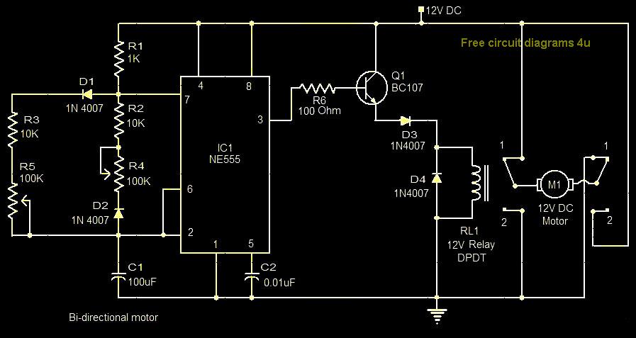
This circuit illustrates a bi-directional motor control circuit utilizing the NE555 integrated circuit (IC). Features include a 12V DC power supply, with the IC employed to control relay RL1. The bi-directional motor control circuit designed with the NE555 IC allows...
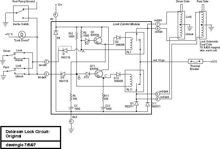
This document discusses the enhancement of a lock control module, providing instructions and photographs for upgrading the module to minimize its standby current consumption, thereby extending battery life. It is assumed that the user possesses a basic level of...
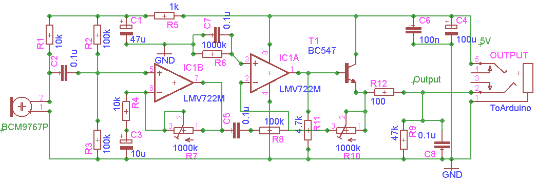
The GVI Digital Remote Control for DSLR cameras represents an advancement over previous remote controls for the Canon EOS 450D. This remote utilizes the AVR Microcontroller ATmega328 and is programmed using the Arduino IDE. It serves as a tool...
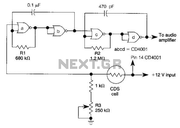
NOR gates A and B create a low-frequency oscillator that activates when the CDS cell, in dark conditions, presents a logic zero to one input of NOR gate A. This low-frequency oscillator, operating at 10 Hz, enables a high-frequency...
An FM modulator that modulates a carrier frequency with the composite signal, and an RF amplifier that provides enough power to be transmitted through an antenna. Here is the schematic diagram of the FM transmitter circuit: The core of...
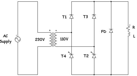
Controlled rectifiers are line-commutated AC to DC power converters that convert a fixed voltage and fixed frequency AC power supply into a variable DC output voltage. The input supply provided to a controlled rectifier is an AC supply with...