
Electronic Buzzer with IC timer NE555 circuit diagram
This electronic buzzer circuit utilizes the NE555 timer IC in an astable configuration to produce a continuous square wave output. The frequency of oscillation is primarily determined by the values of two resistors and a capacitor connected to the timer. In this configuration, the NE555 operates as a multivibrator, generating a square wave signal at a frequency of about 1 kHz, which corresponds to a tone audible to the human ear.
To adjust the frequency of the generated sound, a 10K resistor is used in the circuit. This resistor can be replaced with a variable resistor (potentiometer), allowing for fine-tuning of the sound frequency. By changing the resistance, the charging and discharging times of the timing capacitor are altered, thus varying the frequency of the output waveform.
The circuit typically includes a power supply, the NE555 timer IC, a timing capacitor, and the adjustable resistor. Upon powering the circuit, the NE555 generates a square wave output, which can be connected to a small speaker or piezo buzzer to produce sound. The output sound is a result of the rapid switching of the voltage levels, creating audible tones.
Overall, this buzzer circuit is simple and effective for applications requiring sound alerts or notifications, making it suitable for various electronic projects and prototypes.This easyelectronicbuzzercircuitbuilt based on timer works for gaining the frequency. The IC timer NE555 used as astable multivibrator operating at about 1kHz and produces a sound when switched on. The sound frequency can be adjusted by varying the 10K resistor. You may change the 10K resistor with variable resistor. We aim to transmit more infor mation by carrying articles. Please send us an E-mail to wanghuali@hqew. net within 15 days if we are involved in the problems of article content, copyright or other problems. We will delete it soon. 🔗 External reference
Related Circuits
This circuit enables observation of movement between other stroboscopes. Generation of rectangular signal is based on NE555. This circuit requires a low power supply that is made from a simple transformer TR1, traditional rectifier bridge and zener diode. NE555...
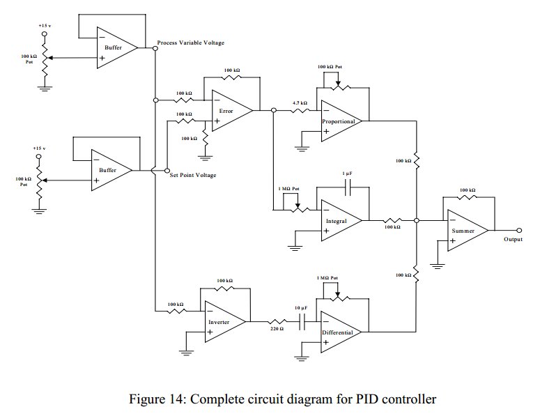
Convert a feedforward operational amplifier PID loop to C code. Assistance is needed for this conversion, as the process is unfamiliar. Input values can be obtained through an ADC, such as voltage or current, but coding a feedforward PID...
The construction is nearly complete, and a circuit diagram has been created. The design has been finalized and documented on paper. The circuit diagram represents a critical stage in the development of an electronic project, serving as a blueprint for...
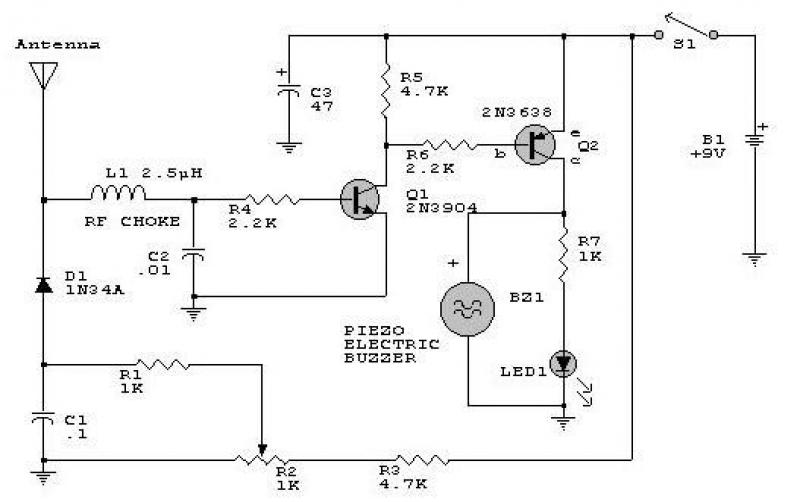
This circuit responds to RF signals below the standard broadcast band up to over 500 MHz and provides both visual and audible indications when an RF signal is detected. By adjusting the bias of diode D2 with the R2...
The circuit consists of two twin-T oscillators configured to operate just below the oscillation threshold. To initiate oscillation, the circuit can be activated by touching the Touch Pad. The circuit utilizes twin-T oscillator configurations, which are known for their ability...
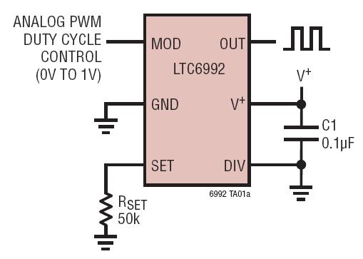
The LTC6990 is a precision silicon oscillator with a programmable frequency range of 488Hz to 2MHz. It can function as either a fixed-frequency oscillator or a voltage-controlled oscillator (VCO). The LTC6990 belongs to the TimerBlox family of versatile silicon...
Warning: include(partials/cookie-banner.php): Failed to open stream: Permission denied in /var/www/html/nextgr/view-circuit.php on line 713
Warning: include(): Failed opening 'partials/cookie-banner.php' for inclusion (include_path='.:/usr/share/php') in /var/www/html/nextgr/view-circuit.php on line 713