
Simulating a Joule Thief circuit with LTSpice
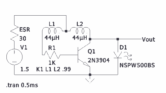
The described circuit involves the use of an FT-50-43 toroidal inductor, which has been calculated to achieve an inductance of 44 µH with 10 turns of wire. This specific inductor is characterized by its ferrite core material, which is suitable for a variety of applications, particularly in RF and power electronics due to its low core losses and high permeability.
The calculation of the inductance value indicates that the inductor is likely being used in a resonant circuit or as part of a filter design, where precise inductance values are critical for performance. The use of a toroidal shape minimizes electromagnetic interference and maximizes magnetic coupling, making it an ideal choice for compact circuit designs.
In practical applications, the inductance value can affect the frequency response of the circuit, influencing both the bandwidth and the quality factor (Q) of the inductor. The number of turns (10 in this case) directly impacts the inductance; increasing the number of turns would increase the inductance value, while decreasing it would have the opposite effect.
It is essential to consider the wire gauge used for winding the inductor, as it affects the resistance and current handling capability of the inductor. Additionally, the physical dimensions of the toroid and the wire must be accounted for to ensure that the inductor fits within the design constraints of the overall circuit layout.
Overall, the design and calculation of the inductor are critical steps in the development of efficient electronic circuits, particularly in applications involving signal processing, power management, or RF transmission.There is much pleasure in useless knowledge. I determined the value of the inductors (44uH) using an online toroid calculator, specifying an FT-50-43 toroid with 10 turns through it. 🔗 External reference
Related Circuits
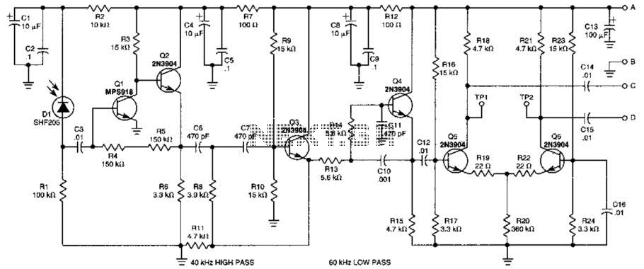
This receiver is designed to detect infrared (IR) or light beams that are frequency modulated on a 50-kHz carrier. The transistors Q2, Q1, Q3, and Q4 form an active filter and amplifier, while the differential amplifier formed by Q5...
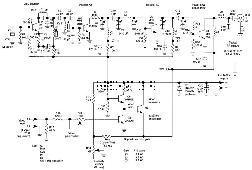
The three schematics illustrate three building blocks for a 10-meter SSB transmitter. These blocks can also be utilized independently as circuit modules for other transmitters. The VFO board incorporates an FET transmission oscillator, with the VFO signal being mixed...
This is an example of a set/reset flip flop using discrete components. When power is applied, only one of the transistors will conduct causing the other to remain off. More: The conducting transistor can be turned off by grounding...

This jam circuit is designed for quiz contests, allowing participants to press their button (switch) to gain the first opportunity to answer a question. The circuit accommodates up to eight contestants, each assigned a unique number (1 to 8)....

This is a low-cost FM antenna booster designed to enhance reception of programs from distant FM stations. The FM antenna booster circuit features a common-emitter tuned RF preamplifier utilizing the VHF/UHF transistor 2SC2570 (C2570). The schematic illustrates the configuration...
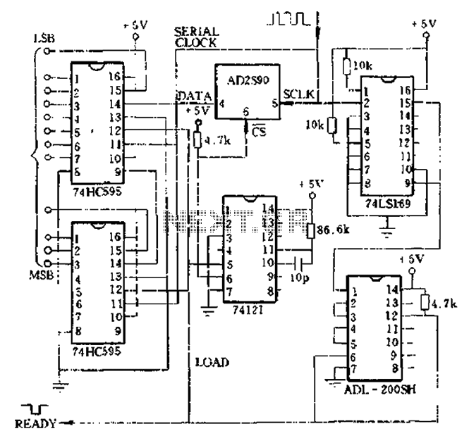
Absolute shaft angle data serial-parallel conversion: the serial AD2S90 axis angle data is converted to parallel data. This method utilizes timed digital pulse signals that can be generated by a microprocessor or a hardware circuit. An example of using...
Warning: include(partials/cookie-banner.php): Failed to open stream: Permission denied in /var/www/html/nextgr/view-circuit.php on line 713
Warning: include(): Failed opening 'partials/cookie-banner.php' for inclusion (include_path='.:/usr/share/php') in /var/www/html/nextgr/view-circuit.php on line 713