
arduino code for buffalo ii dac lcd connection
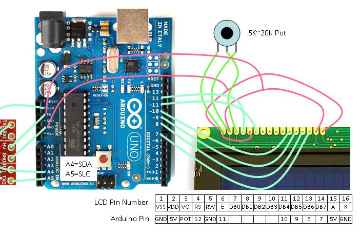
The integration of a standard LCD with an Arduino microcontroller involves establishing specific connections that facilitate communication and control. The typical configuration includes connecting the LCD's data pins to designated digital pins on the Arduino, often using pins 2 to 7 for a 16x2 character LCD. The control pins, including the Register Select (RS), Read/Write (RW), and Enable (E), must also be connected to appropriate digital pins on the Arduino to manage data transmission effectively.
The LCD requires a power supply, typically 5V, which can be derived from the Arduino's power output. It is essential to connect the ground (GND) of the LCD to the ground of the Arduino to ensure a common reference point. Additionally, a potentiometer is often used to adjust the contrast of the LCD. This potentiometer is connected between the V0 pin of the LCD and ground, with the wiper connected to the V0 pin, allowing for manual adjustment of the display contrast.
The standard LCD library provided by Arduino simplifies the programming aspect. By including the library in the Arduino IDE, users can easily send commands and data to the LCD using predefined functions. The initialization of the LCD typically involves setting the number of columns and rows, followed by clearing the display and setting the cursor position for text output.
This setup is widely used in various applications, including simple user interfaces, data display for sensors, and interactive projects, showcasing the versatility of the Arduino platform in handling LCD displays.For a good tutorial in hooking up a ""standard"" LCD to Arduino and use the standard LCD library, see: LadyAda Tutorial on LCDs The diagram shows the basic connections with a ""standard"" LCD that is also compatible with the current Arduino LCD library. Adjustment for the contrast is manual with.. 🔗 External reference
Related Circuits
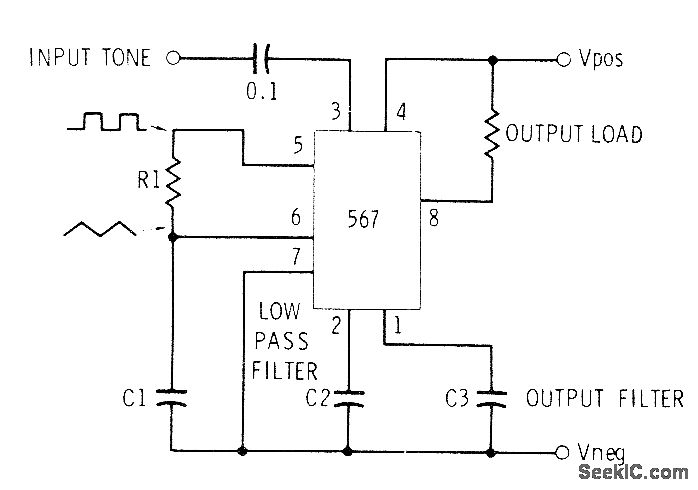
This circuit can be utilized for Touch-Tone decoding as well as for telephone line and wireless control applications using a single audio frequency. The operating center frequency is determined by components H1 and C1. The resistor R1 should be...
Stepper motor interfacing with a microcontroller. Full-step and half-step stepper control. Working principles and basics of stepper motors. Tutorial on 6-lead unipolar stepper motors and bipolar stepper motors. Stepper motors are widely used in various applications requiring precise control of...
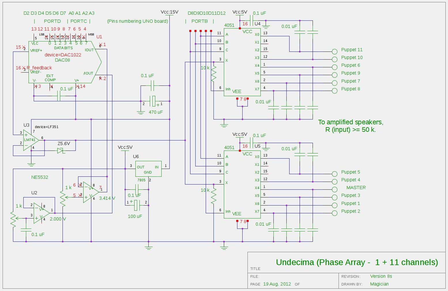
There is a project involving an Arduino that outputs audio signals to USB speakers using 10-bit PWM. Initially, the sound quality produced via PWM was unsatisfactory due to the limited processing speed of the Arduino, which is insufficient for...
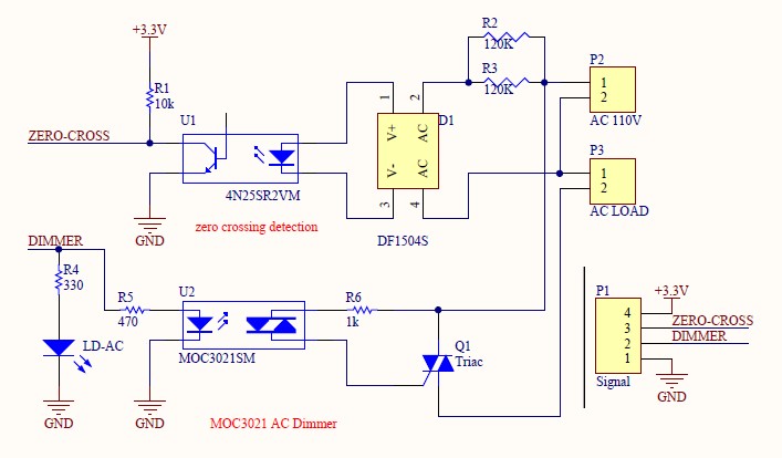
Have you verified whether you can see the zero crossings on your input pin? It may be beneficial to write a sketch that toggles the LED on pin 13 every 50 or 60 zero crossings. This should result in...
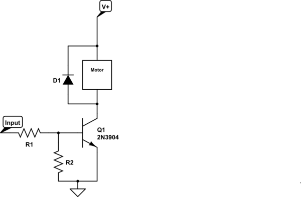
Control a small 5V motor using an external power supply by triggering a transistor with an Arduino. The transistor in use is an NPN type, specifically the 2N3904. To control a small 5V motor using an Arduino and an NPN...
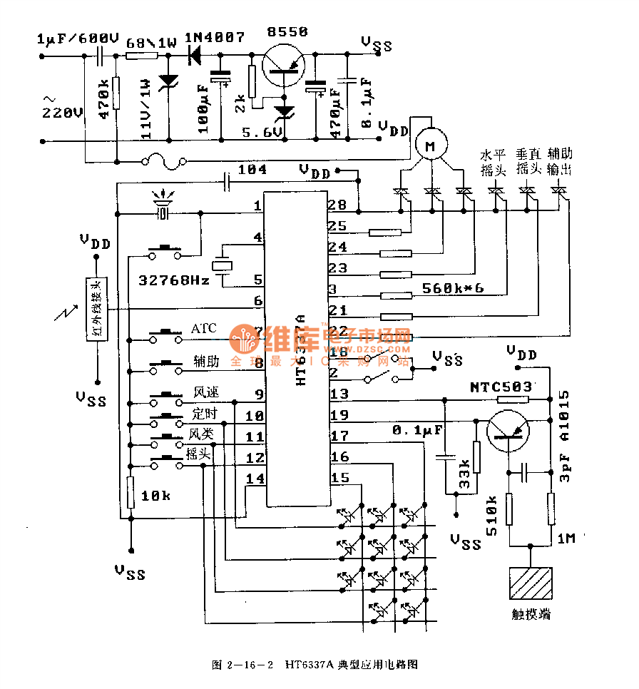
The HT6337 is an infrared remote control receiving decoder circuit specifically designed for electric fan applications. It is housed in a 28-pin dual-row DIP package, with the compatible model being HT12C. The HT6337 is part of a series of...
Warning: include(partials/cookie-banner.php): Failed to open stream: Permission denied in /var/www/html/nextgr/view-circuit.php on line 713
Warning: include(): Failed opening 'partials/cookie-banner.php' for inclusion (include_path='.:/usr/share/php') in /var/www/html/nextgr/view-circuit.php on line 713