
Arduino controlling a DC Motor

In motor control circuits, especially those utilizing microcontrollers, the implementation of snubber circuits is critical for protecting components from voltage spikes and ensuring stable operation. Snubber circuits typically consist of a resistor and capacitor in series, connected across the motor terminals. This configuration helps absorb the inductive kickback generated when the motor is switched off, preventing damage to the microcontroller and other components in the circuit.
When a transistor controlling the motor is turned off, the energy stored in the motor's inductance can generate a high voltage spike. This spike can lead to excessive voltage levels that may damage the transistor or the microcontroller. By placing a diode across the motor, the reverse current can flow through the diode, allowing the energy to dissipate safely. This method effectively clamps the voltage, protecting sensitive components.
For optimal performance, it is advisable to consider the placement of the diode. Moving the diode directly across the motor terminals can enhance the circuit's response to inductive spikes, allowing for quicker dissipation of energy. This adjustment can lead to improved reliability and longevity of the motor control system.
In summary, integrating a snubber circuit and appropriately positioning the diode are essential practices in motor control applications involving microcontrollers. These strategies help mitigate the effects of inductive kickback, ensuring the safe and efficient operation of the motor control system.When controlling motors with a microcontroller (like shown), the snubber is really pretty important. I haven`t seen this configuration, though, and typically the snubber is placed across the motor itself. The general idea is that there is charge that builds up on the motor coil, and, when the transistor is "off", the diode allows a current to flow and the
charge to dissipate. Try moving that diode across the motor for better results.
Related Circuits
DC motors can be operated remotely using controls transmitted via an RF module. This circuit employs an RF module to manage DC motors through a motor driver integrated circuit (IC) L293D. Transmission is initiated by setting pin 14 (TE,...
The following circuit illustrates the circuit diagram of a motor control unit. This circuit is based on the LM317 integrated circuit. Features include diodes that protect the regulator. The motor control unit circuit utilizes the LM317 voltage regulator to provide...
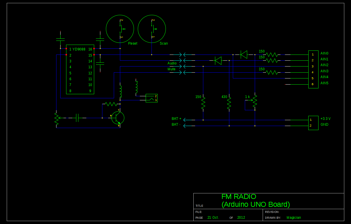
A local convenience store (Dollarama in Montreal, Canada) offers an appealing FM radio for just $3. The idea of interfacing this radio with an Arduino presents a fun challenge. Although the primary goal is not to create a radio,...

The LM339 comparator IC (Integrated Circuit) is utilized to enhance the functionality of electric circuits. A potentiometer (B) is incorporated to adjust the desired setpoint, while a feedback signal is generated by resistor (R). A significant pressure point is...
S1 and S2 are normally open, push-to-close, momentary switches. The diodes can be either red or green and are used solely for indicating direction. The TIP31 transistors may need to be adjusted based on the motor specifications. It is...
This circuit is beneficial for connecting a computer to homemade robotics. It is straightforward to construct and operate, capable of controlling two DC motors of varying current and voltage ratings, contingent on the specifications of the relays used. Additionally,...