
arduino Glacial Communications
The Lo-fi Arduino Guitar Pedal is an innovative project that integrates digital signal processing with analog audio effects. The primary function of this device is to create a distinctive sound through a digital delay effect, which can enhance the tonal quality of electric guitar performances. The initial implementation of the delay effect utilized a 512-value array, which was intended to store audio samples for processing. However, due to memory constraints, the array was scaled down to 256 values, allowing for a maximum delay time of approximately one second. This delay time corresponds to a sample rate of a few hundred Hertz, which is sufficient for producing a lo-fi effect, although it may not capture the input signal with high fidelity.
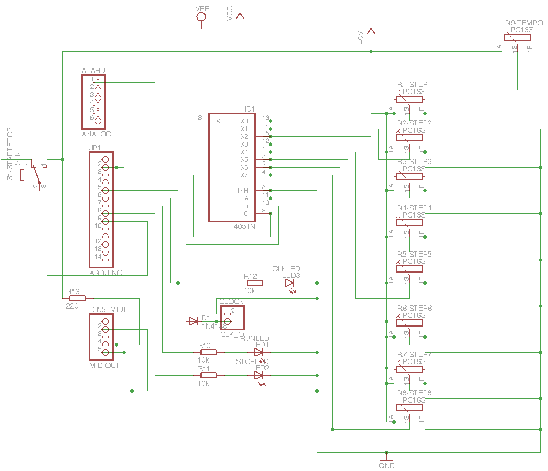
The schematic design process was facilitated by EAGLE software, which is well-suited for creating detailed electronic schematics. The use of pinheader objects to represent connections simplifies the layout, although it is important to note that the pin assignments may not align perfectly with the physical Arduino pin numbers. For example, pin A0 on the Arduino corresponds to pin 1 of the analog block in the schematic representation. This design consideration is crucial for ensuring that the connections are correctly implemented in the physical build.
The Arduino 8-step MIDI sequencer component of the project presents an opportunity for further enhancements. The original design experienced operational failures during demonstrations, indicating the need for debugging and refinements. The proposed simplification of wiring through the introduction of a dedicated 5V bus and ground bus will streamline the connections between the panel and PCB, thereby improving reliability and ease of assembly.
In addition to wiring improvements, the integration of a start/stop button will enhance user control over the sequencer's operation. The decision to utilize LED-equipped lever switches is a strategic choice, as it provides visual feedback regarding the device's status, indicating whether it is in a running or stopped state. This feature adds an element of usability that is often overlooked in DIY electronic projects.
Finally, the transition to a 276-159 PCB and its permanent hardwiring to a Modern Device RBBB presents a cost-effective solution for powering the project. This approach not only reduces the overall expense but also simplifies the assembly process by minimizing the number of components required. Overall, this project exemplifies the blend of creativity and technical skill involved in developing custom electronic devices, particularly in the realm of audio processing and MIDI control.I built my own Lo-fi Arduino Guitar Pedal. I`m even using a similar enclosure work tossed out a couple of thinwire->twisted pair converters that I snapped up. I think the only major deviation is that mine only has one output at present- I could add a second later, though.
I got to thinking last week that a digital delay wo uld be an interesting idea I had no notion that this would compete with anything in the quality department- a very short, crunchy delay I just wanted to try it out. So I wrote a little program and originally used an array of 512 values, and cycled through them, while recording point i, and playing point (i+1) (with edge checks and things like that, of course) It turned out that 512 shorts of storage must have overflowed available program memory and caused general non-functionality.
Changed the delay to 256 shorts. That at least got me up and running. And it gave me about a second of delay time kind of unexpected (that makes the sample rate, what, a few hundred Hertz ). It also doesn`t give a very accurate representation of the input. A test went something like this: snare (pause) krrrzzk. I`ve done plenty of quickie hand-scribbled schematics, and at some point some computer-assisted ones (hell, I have a degree in Computer Engineering, it came up once or twice ).
So I decided for the Arduino sequencer, I should do a little schematic using recent tools. EAGLE now runs reasonably on OS X, and for noncommercial/evaluation things, the light version is free. I`ve represented the Arduino connections and various jacks (MIDI, 1/4 ³ for clock, etc. ) with the pinheader objects which don`t 100% correspond to the Arduino pin numbers. Note that for example, Arduino pin A0 is actually pin 1 of the ANALOG block here. Hopefully that`s not too confusing. While I`ve reached a pause point on the Sound Lab, I decided to revisit the Arduino 8-step MIDI sequencer I built for my presentation at Notacon.
There are a number of improvements to be made and bugs to be fixed (for those who were there, you may remember it completely failed for the demo it worked great during setup, but not the demo itself) Simplify Panel Wiring I somewhat ridiculously wired the panel originally. Instead, it`s going to get a 5V bus and a ground bus, which will cut panel-PCB wiring by a lot. I`ll also fix the issue with the MIDI output while I`m at it Properly implement a start/stop button I originally was going to use an on/off switch, but that didn`t work right in the original design so I scrapped it.
Since then, I got some of these LED-equipped lever switches, so it will have running and stopped indicators as well. Switch the PCB to a 276-159, and permanently hardwire it to a Modern Device RBBB they`re selling 5 RBBB kits for the price of one Arduino Nano how can I refuse
🔗 External reference
Related Circuits
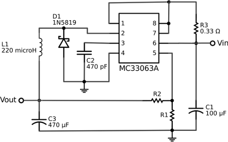
The voltage regulator integrated into the Arduino Uno is a linear-type regulator, which exhibits poor efficiency. When operating the ATmega238 at 5V with a 9V battery, nearly half of the battery's energy is wasted as heat by the regulator....
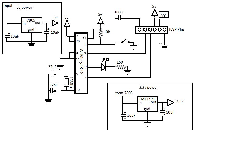
If you are interested in working with Arduino, you may have considered creating your own Arduino board. Creating a custom Arduino board can be an enriching project that allows for greater flexibility and personalization in electronic designs. The process typically...
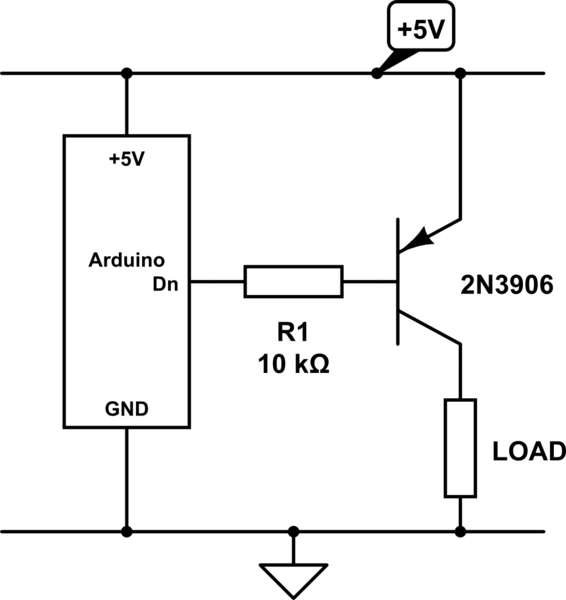
The emitter will consistently be a few hundred millivolts lower than the base voltage in this configuration. With the base voltage set at 5V, the emitter voltage is likely to be around 4.5V, depending on the current drawn by...
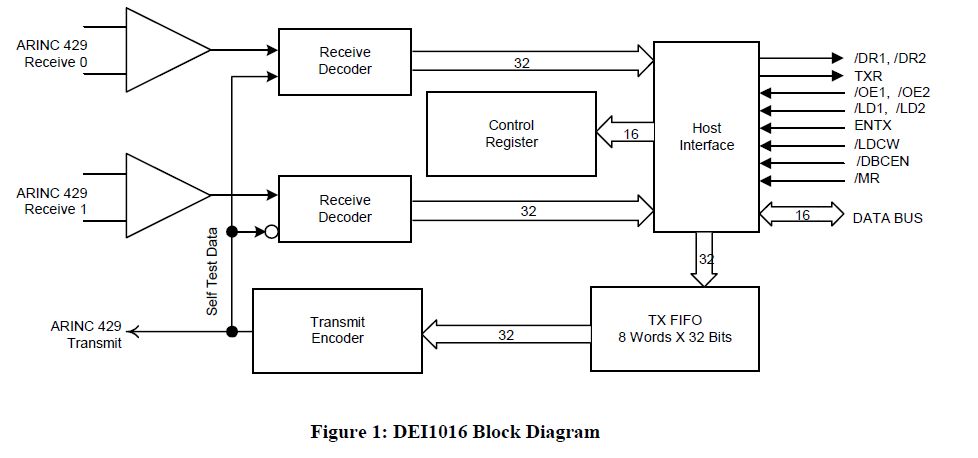
This document outlines the process of interfacing an Arduino with an ARINC 429 transceiver, illustrating the general methodology for connecting an Arduino to electronic circuits that can be applied to individual designs. The ARINC 429 bus is the predominant...
The text of the Arduino reference is licensed under a Creative Commons Attribution-ShareAlike 3.0 License. Code samples in the reference are released into the public domain. The Arduino platform is an open-source electronics prototyping environment that enables users to create...
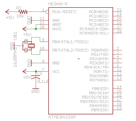
There are many bare-bones Arduinos available on the internet. Most of them are assembled on a solderless breadboard and utilize an ATmega168 (or ATmega328) microcontroller with an Arduino bootloader, a resonator (which may have built-in capacitors or require two...