
arduino pwm hb

The TA8050 is a versatile DC motor controller designed for use with microcontrollers, such as the Arduino. This controller allows for precise control of DC motors, making it suitable for various applications, including robotics and automation projects. The TA8050 can handle a wide range of input voltages and provides features such as speed control and direction reversal.
To connect the TA8050 to an Arduino, the following steps should be taken:
1. **Power Supply**: Ensure that the TA8050 is powered with an appropriate voltage supply that matches the motor specifications. The power supply should be connected to the VCC and GND terminals of the TA8050.
2. **Motor Connections**: Connect the DC motor to the output terminals of the TA8050. The motor terminals should be connected to the designated output pins, typically labeled as M1 and M2.
3. **Control Pins**: The TA8050 requires control signals from the Arduino to operate. Connect the control pins (IN1, IN2, PWM) of the TA8050 to the appropriate digital output pins on the Arduino. IN1 and IN2 are used for direction control, while the PWM pin is used for speed control.
4. **Programming the Arduino**: Using the Arduino IDE, upload a sketch that defines the control logic for the motor. The sketch should include functions to set the direction of the motor and adjust the PWM signal for speed control. For example, setting IN1 high and IN2 low would make the motor rotate in one direction, while reversing the signals would change the direction.
5. **Testing**: After uploading the program, test the motor operation by varying the PWM signal to observe the speed control functionality. Additionally, verify the direction control by toggling the IN1 and IN2 pins.
By following these steps, the TA8050 DC motor controller can be effectively integrated with the Arduino microcontroller, allowing for robust control over motor functions in various electronic projects.Connecting and programming the TA8050 DC motor controller with the Arduino microcontroller.. 🔗 External reference
Related Circuits
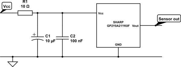
A project involves two distance sensors that signal an Arduino to operate a servo motor when an object comes within range. The system functions correctly; however, the sensors output a consistently high voltage, necessitating a high cutoff voltage in...
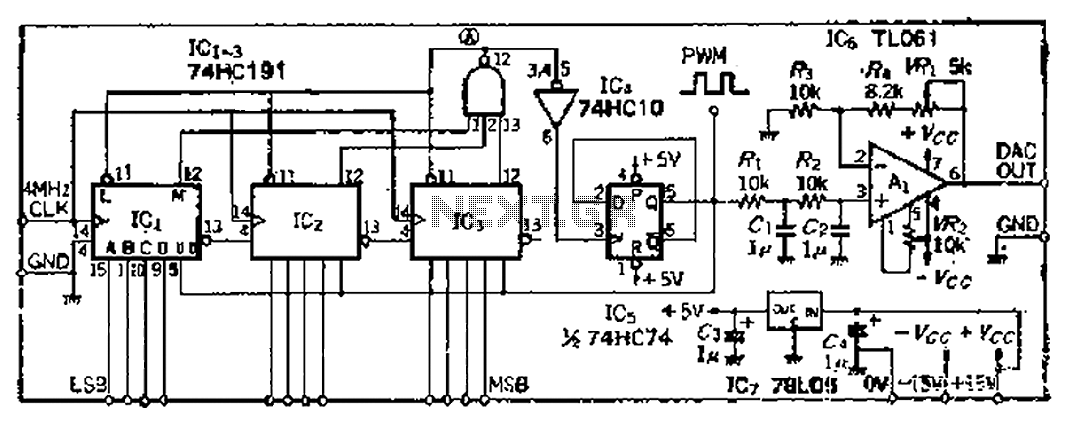
A PWM clock signal is generated at 4096 times the input frequency, counting up (Q3) until the base of ICi-IC3 is full. The output point produces a maximum clock signal. On one side, voltage data is loaded into IC3,...
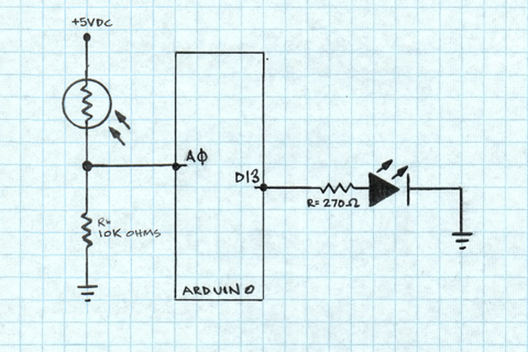
A project is underway to determine the number of sun hours available at a specific location and to track this data over time as part of solar power installation design. The concept involves utilizing a light detector exposed to...

When discussing fan control, there are generally two methods: linear control and pulse-width modulation (PWM) control. Linear control is the most commonly used method, which involves reducing the voltage supplied to the fan. For a fan rated at 12...
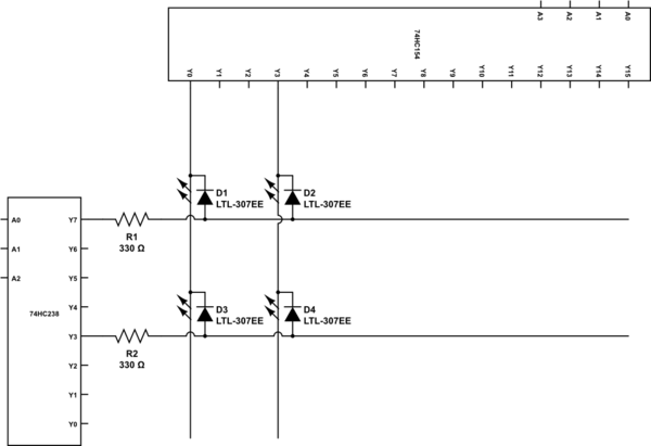
To construct a 7 to 128 demultiplexer using 3-to-8 and 4-to-16 demultiplexers, the three highest bits of the output address should be fed into the 3-to-8 demultiplexer. The outputs from this demultiplexer will serve as the enable inputs for...
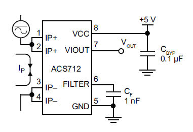
The primary component utilized is the ACS712 sensor from Allegro MicroSystems, designed for measuring current. It offers cost-effective and accurate solutions for AC or DC current sensing in industrial, commercial, and communication systems. A precise, low-offset, linear Hall sensor...