
led Arduino multiplexing help needed

In a simulation setup using CDS, a 74LS138 is utilized as the 3-to-8 demultiplexer, with seven 74HC154 devices functioning as the 4-to-16 demultiplexers. The address outputs from an Arduino are represented by SPDT switches, with one terminal connected to Vcc and the other to digital ground. Issues have arisen where the LEDs do not illuminate, likely due to incorrect connections involving the enables. The anodes of the LEDs are soldered together, while the cathodes must connect to the outputs of the 4-to-16 demultiplexers, indicating a potential misunderstanding regarding the enable signals.
The circuit design involves a hierarchical arrangement of demultiplexers to achieve the desired output range. The 3-to-8 demultiplexer (74LS138) will decode the three most significant bits (MSBs) of the address input, generating eight outputs. Each output corresponds to one of the enable inputs of the 4-to-16 demultiplexers (74HC154). Each of these demultiplexers can handle four bits of input, allowing for a total of 16 outputs per device.
The enable pins of the 4-to-16 demultiplexers must be appropriately controlled by the outputs from the 3-to-8 demultiplexer to ensure that only one 4-to-16 demultiplexer is active at any given time. This multiplexing scheme allows for the selection of one out of 128 possible outputs based on the combination of the three MSBs and the four least significant bits (LSBs) fed into the selected 4-to-16 demultiplexer.
It is crucial to verify that the output current ratings of the demultiplexers are sufficient for the intended application. If the current capacity is inadequate for driving the LEDs directly, a transistor can be employed as a switch to amplify the current from the demultiplexer outputs to the LEDs, ensuring reliable operation. Additionally, attention should be paid to the polarity of the enable signals; inverters may be necessary if the enable logic levels do not match the requirements of the demultiplexers.
In summary, this demultiplexer configuration enables a flexible and efficient method for controlling multiple outputs, making it suitable for various electronic applications where multiple signals need to be managed effectively. Proper attention to the design and connections will facilitate the successful implementation of the circuit.If you want to build a 7 to 128 demux with 3-to-8 and 4-to-16 demuxes, then put the 3 high bits of your output address into the 3-to-8, and use the outputs of that as the input enable to the individual 4-to-16 demuxes (assuming that it has an enable pin), so the output #0 on the 3-to-8 would go to the input enable of the first4-to-16 demux, the output #1 would go to the second, etc. No other components I can think of, except possibly inverters if the input enable is the wrong polarity. Also check that your demux can source enough current to power the LED, if not then you may need to use a transistor to boost the current.
@SamuelPogue Tim May 2 `13 at 23:43 I am attempting to simulate this using CDS using a 74LS138 as the 3-to-8, and 7 74HC154`s for the 4-to-16`s. I have it set to where SPDT`s represent the address outputs on the arduino where one lead is connected to Vcc, and the other is connected to digital ground.
However something is going wrong here and the LED`s won`t light. Because I have all the anodes of the LED`s soldered together, and the cathodes have to be the ones to connect to the outputs of the 4-to-16`s, I am assuming I am doing something wrong with the Enables. Of course, I am trying to discern why there are multiple Enables. Samuel Pogue May 3 `13 at 20:42 🔗 External reference
Related Circuits

The wire speed DC motor consistently receives approximately 20 volts, irrespective of the switch position on the nozzle handle. The switch has been tested with an ohmmeter and functions properly. Even after disconnecting the switch from the circuit board,...
Arduino is an open-source electronics prototyping platform that features flexible and user-friendly hardware and software. It is designed for artists, designers, hobbyists, and anyone interested in creating interactive objects or environments. Arduino can sense the environment by receiving input...
This circuit illustrates the TDA1054 tone control stereo preamplifier circuit diagram. Features include the National Semiconductor LM35 integrated circuit, which utilizes semiconductor technology. The TDA1054 is a versatile integrated circuit designed for use in audio applications, particularly in tone control...
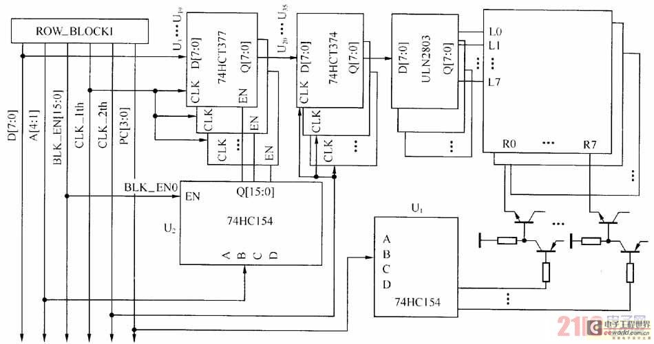
The large-scale LED display system utilizes a line-by-line scanning method and outlines the driving mechanisms to reduce hardware costs. It employs a 1/16 non-interlaced scanning mode, accommodating a total of 16 LED display panels. The schematic diagram of the...
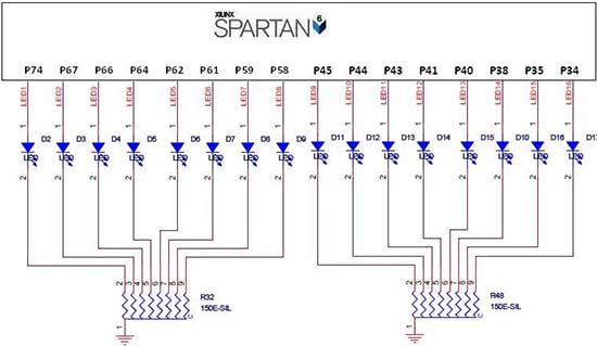
The Spartan-6 board features 16 LEDs connected to FPGA I/O pins, as detailed in the table below. The cathode of each LED is connected to ground through a 330-ohm resistor. To illuminate a specific LED, the corresponding FPGA control...
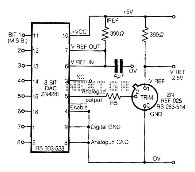
This circuit demonstrates a straightforward approach to achieving a voltage reference that can be adjusted using an 8-bit Digital-to-Analog Converter (DAC) equipped with an integrated voltage reference. The analog output from the DAC controls the trim pin of the...