
Arduino Seismic Activity Monitor

The described circuit utilizes a piezoelectric sensor, which generates an electrical charge in response to mechanical stress. The integration of washers and a bolt effectively alters the mass and damping characteristics of the system, thereby tuning the resonant frequency. The careful adjustment of weights allows for the maximization of desired frequencies in the range of 40 Hz, which is often useful in various applications, including vibration sensing and signal processing.
The oscilloscope serves as a critical tool for visualizing the frequency response of the system. By employing Fast Fourier Transform (FFT) capabilities, the oscilloscope can provide detailed insights into the frequency components of the signal generated by the piezo sensor. For those without access to such equipment, a practical approach involves manually adding weight and striking the sensor, which can induce a temporary oscillation, allowing for a basic understanding of the sensor's response characteristics.
The use of a charge amplifier in this circuit is pivotal. This component is designed to convert the high-impedance output from the piezoelectric sensor into a low-impedance voltage signal. The charge amplifier functions as an integrator, ensuring that the charge generated by the piezo film does not dissipate too quickly, which could lead to a loss of signal fidelity. This characteristic is particularly important in applications where precise measurement of small signals is required, as it enhances the signal-to-noise ratio.
The arrangement of the components, including the piezo film, charge amplifier, and oscilloscope, forms a basic but effective electronic schematic for capturing and analyzing mechanical vibrations. Proper mounting of the sensor, as indicated by the need to tape down the base, is crucial for maintaining signal integrity and ensuring that the vibrations are accurately transmitted to the piezo film without interference from loose connections. Overall, this configuration provides a practical solution for experimenting with piezoelectric sensors and understanding their behavior in response to mechanical stimuli.So to reduce the resonant frequency and get some useful signals, I took some washers slapped them on a bolt and some nuts and experimented. I used aOscilloscopewith FFT and changed the weight on the tip of the film until frequencies of around 40Hz were the largest.
If you don`t own anoscilloscope, just add a little weight and then hit the sensor. It should flop around for about half a second to a second before coming to rest. As you can see from the picture, I taped down the base of the sensor. This is because the leads on the piezo film is flat, and tends to be loose inside the breadboard, so any vibrations tend to get lost in the movement of the leads. A Charge Amp takes the chargeacrossa capacitor and translates it into a voltage. If you know your electronics you can see that it is essentially an integrator, which prevents the charge across the Piezo film, which acts like a capacitor, from discharging quickly.
🔗 External reference
Related Circuits
This is a tutorial for beginners who have recently started learning about electronics. The author has prior experience in programming with C and Python. The schematic presented in this tutorial is designed for novice electronics enthusiasts who are transitioning from...
The circuit utilizes a Hall-effect sensor, which is an integrated circuit (IC) positioned within a small gap of a flux-collector toroid, to measure direct current (DC) ranging from 1 to 40 A. The current-carrying wire is threaded through the...
The BC547 transistor has a maximum operating current of 100 mA and a maximum voltage rating of 65 volts. When oriented with the label facing the viewer, the three terminals from left to right are collector, base, and emitter....

This circuit utilizes a type 741 operational amplifier (op amp) configured as a voltage comparator. One input of the 741 is connected to a reference voltage, sourced from a 12-V battery, via a resistor voltage divider. The voltage at...
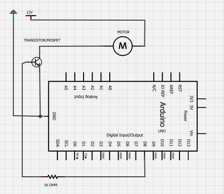
A cat deterrent system utilizing an Arduino, similar to existing models. Detection has been successfully implemented, and it has been determined that an ultrasonic transducer is required to generate the necessary deterrent sound. The proposed cat deterrent system employs an...
The emitter will consistently be a few hundred millivolts lower than the base voltage in this configuration. With the base voltage set at 5V, the emitter voltage is likely to be around 4.5V, depending on the current drawn by...