
Arduino Thermostat

The project involves the design and implementation of a temperature and humidity sensor node, inspired by the FridgeControlWeb project. The circuit incorporates the HS1101 humidity sensor, which operates based on capacitance variation with humidity levels, and the Dallas 1820 temperature sensor, which communicates via a 1-Wire interface. The circuit is designed to minimize power consumption by powering down the HS1101 and associated components when not actively measuring, thereby reducing noise and potential interference.
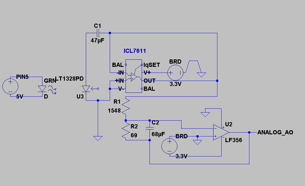
The schematic features a CMOS version of the 555 timer, which is crucial for accurate readings; using an NMOS variant would result in erratic outputs. Resistor values R1 and R2 must be selected carefully to match the specifications for the LMC555, with R1 set at approximately 1.238 MΩ and R2 at around 562 kΩ to ensure accurate operation. The circuit also includes a microcontroller that manages the data collection and processing, with libraries included for network communication and temperature readings.
The system is programmed to perform measurement cycles at specified intervals, with a defined sleep period to conserve power. The web server setup is configured to handle requests and display the gathered data. The calibration process is ongoing, with the intention of aligning the sensor readings with actual environmental conditions, despite discrepancies noted in external weather data. The dual sensor system—one for indoor and one for outdoor readings—aims to facilitate effective control of the evaporative cooling system, ensuring optimal humidity levels within the home.This is just a quick post at the moment because the project isn`t done and I am distracted by other things. The thermostat for the central heater in my house became unreliable a week or two ago. My wife rang around and a new one from the manufacturer of the heater was going to be $450 AUD. So, it seemed obvious to make my own. I`ve just installed the 1. 0 of it, with the board layout and manufacture being done by Doug once again. The next sensor I wanted to add to my home was a set of hygrometers. Specifically I wanted an exterior one, and a matching interior one. This would be useful as we have evaporative cooling, and if the humidity level outside is already high, then it doesn`t make a lot of sense to put extra water into the air. Worse than that, it can also damage my books and make the house really clammy. So, adding some sensors was the first step in some form of alerting. I picked up two HS1101s from ebay quite cheaply (about $4 each IIRC). These devices are capacitors whose capacitance varies proportionally with relative humidity. You also need to provide a temperature at the sensor to correct the value, although the correction is pretty minor so I guess you could skip this if you really wanted to cut costs.
Given I have plenty of code for Dallas 1820s now, I just dropped one of those onto the board too. I just used the circuit from the data sheet for my design, with a few simple tweaks (like the DS1820). Here`s my surprisingly unprofessional circuit diagram: This gives us temperature on a 1-Wire pin, and an oscillator on another pin which relates to the current humidity.
You`ll notice that my circuit has some extra wires, that`s because I power down the 555 / HS1101 when I`m not taking a sample. I do this because Peter H. Anderson suggested that noise would be a problem otherwise. This circuit was actually quite hard to build and get working. There are a few reasons for that: The values for R1 and R2 vary depending on what model 555 you are using, and are crazily specific.
For the LMC555 that I used, R1 is 1238K and R2 is 562K. I got close to these values, but not exact and it did seem to affect accuracy. You must use a CMOS 555. That`s buried in a six word sentence in the middle of a page on the data sheet, and I didn`t notice it for a while. With a NMOS 555, you get effectively random numbers out of the circuit. Worse than that, CMOS 555s are actually a little hard to find, and I had to get mine from Farnell. I attempted to calibrate with the government weather data from the next suburb over. Unfortunately, as best as I can tell, that data is wrong. It claims that its currently as humid here as it is in Cairns in the wet season, which I deny. Calibration is an ongoing issue for me, although I have some ideas on how to progress there. It might also not matter, as I am building an identical sensor for inside the house and as long as they are both equally wrong I can still detect the "turn off the water to the evap" state that I want to.
// Temperature and humidity sensor node. Based on the FridgeControlWeb project of mine // as well as #include
500 Error
" static uint8_t mymac[6] = {0x54, 0x55, 0x58, 0x10, 0x00, 0x25}; static uint8_t myip[4] = {192, 168, 1, 252}; static uint8_t buf[BUFFER_SIZE + 1]; char data[BUFFER_SIZE + 1]; // The 🔗 External referenceRelated Circuits
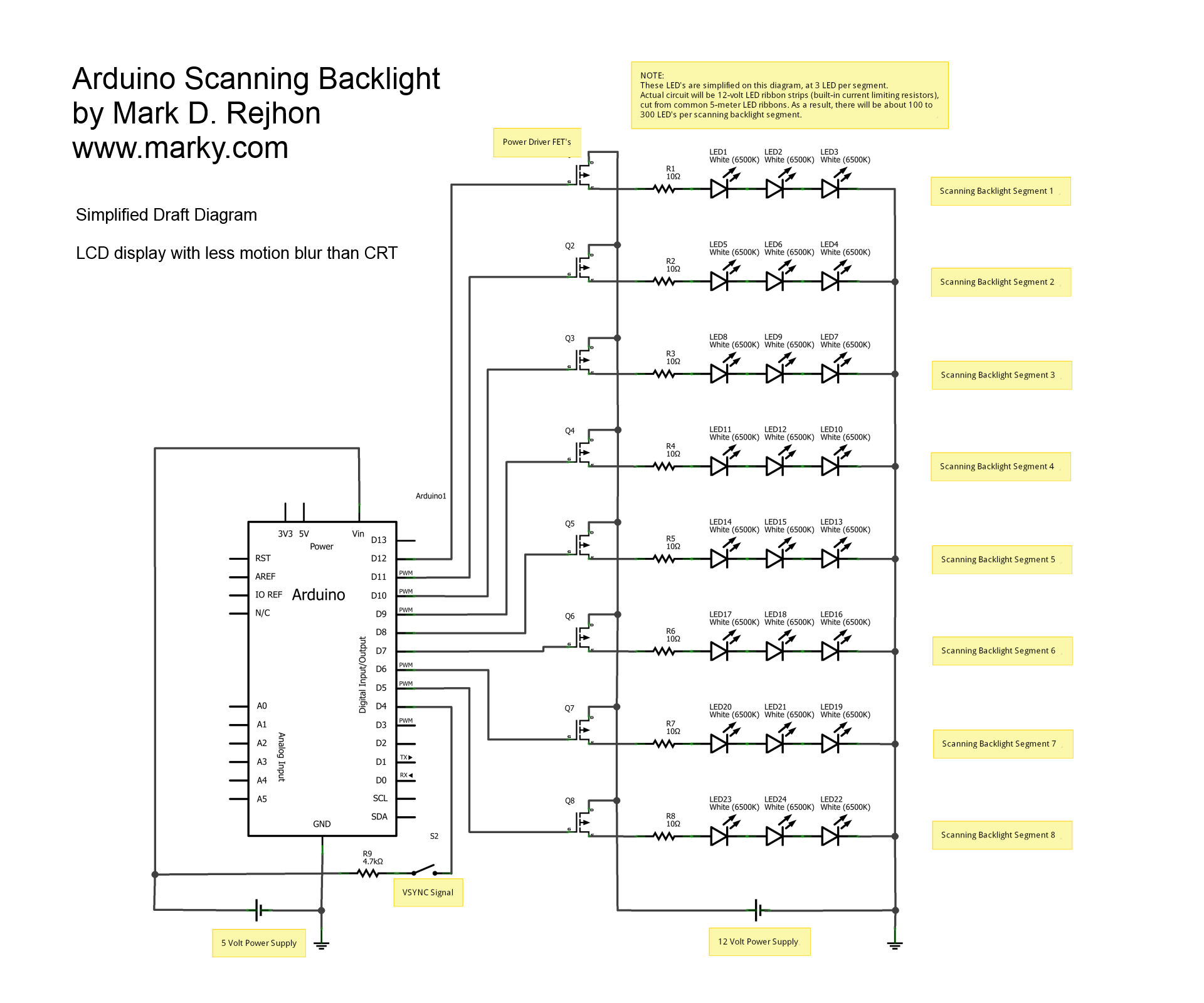
This is a simplified schematic diagram for a homemade scanning backlight driven by an Arduino, an open-source electronics prototyping platform. The Arduino monitors the VSYNC signal (input-lag compensated) and executes a backlight scanning sequence, using ultra-short strobes of super...
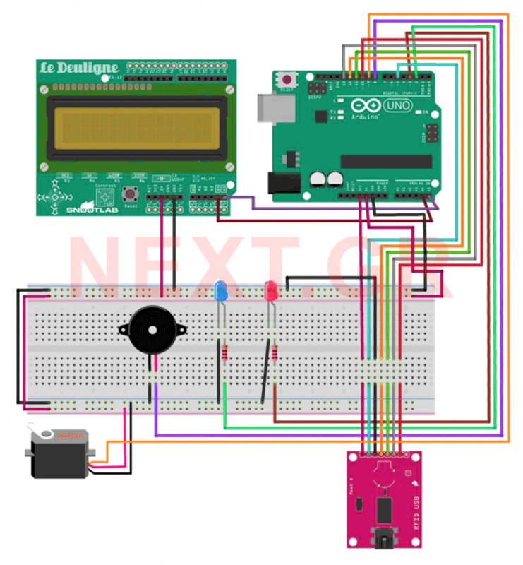
This project aims to develop a security system suitable for business environments or for simple home use. The system utilizes an Arduino Uno microcontroller in conjunction with RFID (Radio Frequency Identification) technology, enabling wireless user identification. Only registered users...
The code implementation discussed in the previous post has been initiated. To improve organization, the code has been modularized into functions, simplifying the overall structure. It is available along with the other code. Challenges were encountered in calculating averages...

In August 2007, an individual with a passion for photography acquired a Panasonic FZ30 digital camera and joined a forum on dpreview dedicated to Panasonic products. A fellow forum member, who was a programmer and electronics enthusiast, created a...
A 5V power supply is used to function as a switch controlled by an Arduino. Direct control from the Arduino pin is not feasible because most general-purpose relays require a minimum of 150mW to activate, which translates to over...
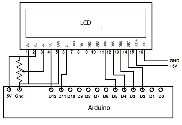
To achieve this, the first step involves establishing the necessary physical connections between the Arduino board and the LCD. Following this, code must be written to display the desired text on the LCD. LCDs have become the standard means...