
Arduino Traffic Light Controller

The traffic light controller project involves designing a circuit that simulates the operation of a traffic light system, typically consisting of red, yellow, and green lights. This project can be implemented using an Arduino microcontroller, which will manage the timing and sequencing of the lights.
The basic components required for this project include:
1. **Arduino Board**: An Arduino Uno or any compatible board can be used as the main controller.
2. **LEDs**: Three LEDs representing the red, yellow, and green lights. Each LED will require a current-limiting resistor, typically 220 ohms, to prevent excessive current flow.
3. **Breadboard and Jumper Wires**: For prototyping and connecting components without soldering.
4. **Power Supply**: The Arduino can be powered via USB or an external power supply.
The schematic will illustrate the connections as follows:
- Connect the anode (longer leg) of the red LED to a digital pin on the Arduino (for example, pin 2) and the cathode (shorter leg) to the ground through a resistor.
- Repeat the same connection for the yellow LED to another digital pin (e.g., pin 3) and the green LED to a third digital pin (e.g., pin 4).
- Ensure all cathodes of the LEDs are connected to the common ground.
The Arduino code will control the timing of each light using the `delay()` function to switch between the red, yellow, and green states. A typical timing sequence might involve the red light being on for 10 seconds, the yellow light for 2 seconds, and the green light for 10 seconds, followed by a repeat of the cycle.
This project not only reinforces basic programming concepts such as loops and conditionals but also provides practical experience with hardware interfacing, circuit design, and debugging. It can be extended by adding features like pedestrian crossing signals, sensors to detect vehicle presence, or even integrating a real-time clock for more complex timing scenarios.If you want to improve your Arduino programming, creating a traffic light controller is great practice.. 🔗 External reference
Related Circuits
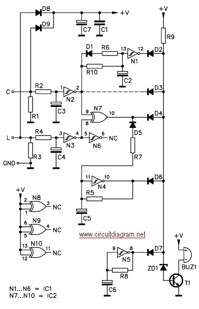
This car headlight alarm circuit can be configured for one or two functions: First, it indicates that the headlights (or the side lights) should be turned off after the ignition is switched off. With this circuit, there should be...
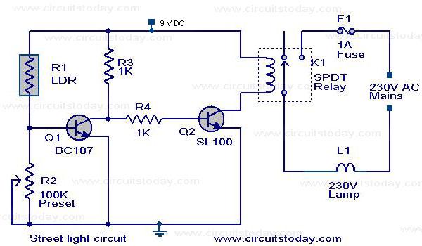
The circuit diagram of an Automatic Street Light Controller Circuit is explained in this post. The Automatic Street Light Controller Circuit is designed to automatically turn on street lights at dusk and turn them off at dawn. This functionality is...
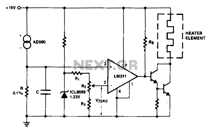
The AD590 generates a voltage that varies with temperature across resistor R, while capacitor C serves to filter out noise. To establish a zero-scale voltage, resistor R2 is adjusted. For the Celsius temperature scale, R should be set to...
These relatively simple circuits can be used to transmit information across a small distance. The information typically used includes music from a radio, iPod, or CD player; a microphone and amplifier can also be utilized. People frequently transmit information...
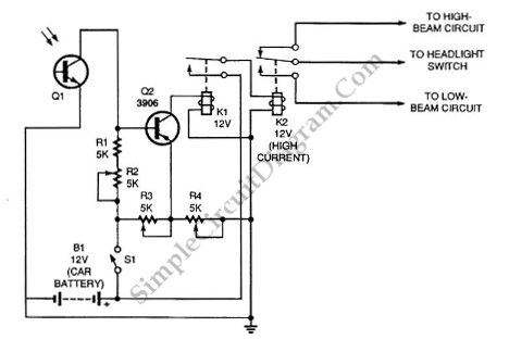
Automatic headlight dimmer circuit diagram for a car's headlight. This circuit ensures maximum brightness for optimal visibility while automatically switching when necessary. The automatic headlight dimmer circuit is designed to enhance driving safety by adjusting the brightness of the vehicle's...
When using microcontrollers in designs, a common challenge is displaying user-required data. Solutions such as multiple LEDs, 7-segment displays, or LCD modules can be employed, but displaying a large amount of information simultaneously can pose difficulties. Large LCD modules...