
Automatic Headlight Dimmer Safe Yourself and Others
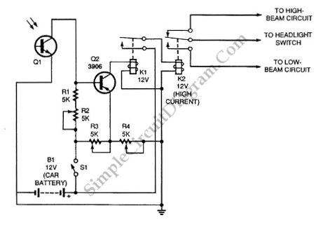
The automatic headlight dimmer circuit is designed to enhance driving safety by adjusting the brightness of the vehicle's headlights based on surrounding light conditions. The primary components of this circuit typically include a light-dependent resistor (LDR), a transistor, a relay, and a diode.
The LDR serves as a sensor that detects ambient light levels. In daylight, the resistance of the LDR is low, which keeps the transistor in a non-conductive state, preventing the relay from activating. As the surrounding light diminishes, the resistance of the LDR increases, allowing the transistor to conduct, which subsequently energizes the relay. This action engages the headlight circuit, switching the headlights to a higher brightness setting.
A diode is included in the circuit to protect against back EMF generated by the relay coil when it is de-energized. This prevents potential damage to the transistor and other components in the circuit. The design may also incorporate adjustable resistors to fine-tune the sensitivity of the LDR, allowing for customization based on user preferences or specific driving conditions.
The schematic typically illustrates the connections between these components, indicating the power supply, ground paths, and signal flow. Proper layout and component selection are crucial to ensure reliable operation and responsiveness of the automatic dimming feature, ultimately contributing to a safer driving experience.Automatic headlight dimmer circuit diagram for your car`s headlight, keep you safe with maximum bright for farthest visibility, but will automatically switch . 🔗 External reference
Related Circuits

This circuit lights up ten bulbs sequentially, first in one direction and then in the opposite direction, creating an appealing visual effect. In this circuit, gates N1 and N2 form an oscillator. The output of this oscillator serves as...
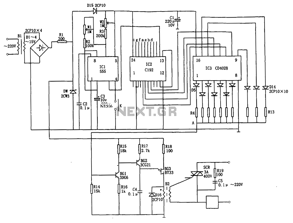
The automatic conversion circuit for wind speed control is depicted in Figure 10. This circuit consists of a clock signal generator (IC1), a counter (IC2), a decoder (IC3), a synchronous phase shifting circuit (BG1, BG2, BG3), a thyristor control...
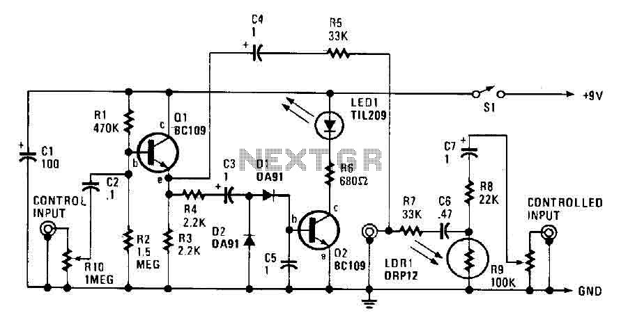
The automatic fader reduces the background music level when narration is in progress. The control input through RIO, a preset audio level control, is directed into an emitter-follower buffer stage (Q1). This buffer provides high input impedance and ensures...
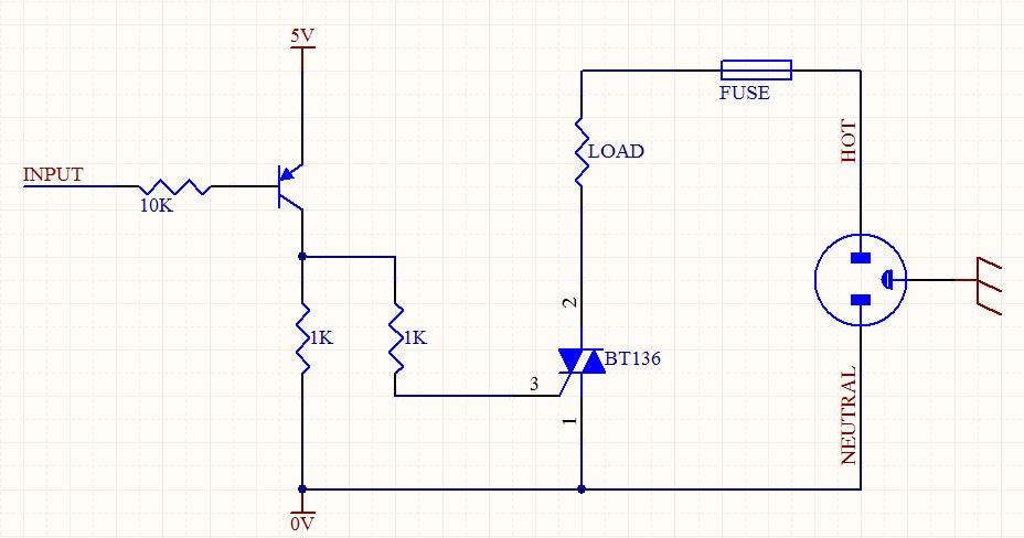
A circuit was designed to function as a light dimmer, utilizing a BT136 SCR and an MOC3022 optocoupler. However, the circuit did not operate as intended. The circuit aims to control the brightness of a light source through phase control...
This circuit features a white LED-based emergency light that provides several benefits. It is exceptionally bright due to the incorporation of white LEDs. The light activates automatically when the mains supply is interrupted and deactivates when mains power is...
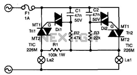
The circuit presented here ensures that if bulb La1 fails, bulb La2 will take over its function. In series with La1 is triac Tri2. Resistor R3 and capacitor C2 form a delay network. When the voltage across C2 exceeds...