
Arduino UNO
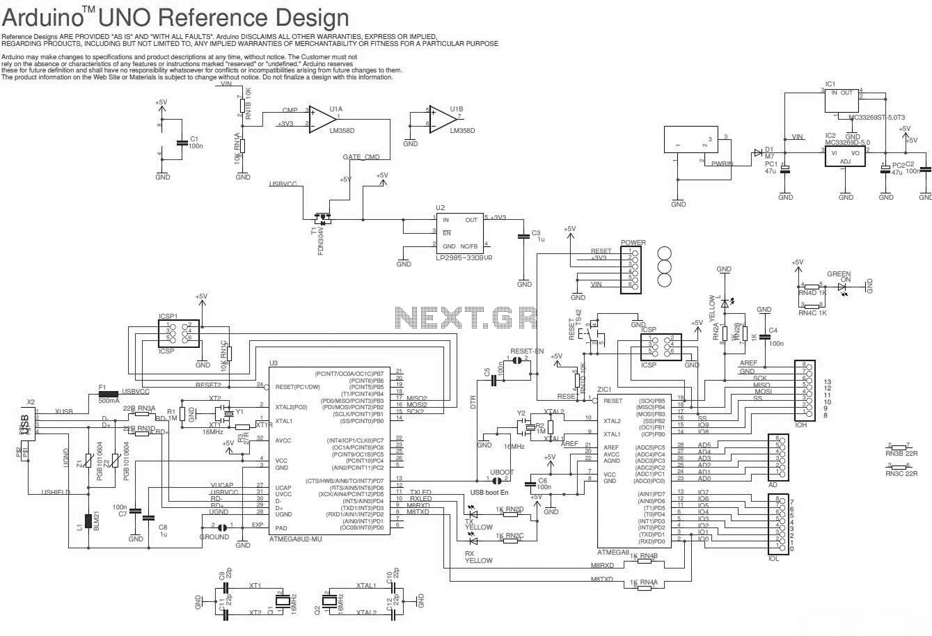
The Arduino Uno is an essential platform for electronics prototyping and development. The ATmega328 microcontroller at its core operates at a clock speed of 16 MHz and provides a robust environment for executing various programs. The board is equipped with 14 digital I/O pins, allowing for versatile interfacing with other electronic components. Among these, 6 pins are capable of Pulse Width Modulation (PWM), which is particularly useful for applications requiring variable signal outputs, such as controlling the brightness of LEDs or the speed of motors.
Additionally, the Arduino Uno contains 6 analog input pins that can read varying voltage levels from sensors, enabling the board to interpret real-world signals. The board is powered via a USB connection or an external power supply, which can provide voltages between 7 to 12 volts. The onboard voltage regulator ensures that the microcontroller and connected components receive a stable 5V supply.
The schematic diagram of the Arduino Uno includes details about the power supply, pin configurations, and connections to critical components such as the crystal oscillator, reset button, and the USB interface. Understanding the schematic is crucial for anyone looking to modify the board or integrate it into larger systems, as it provides insight into the electrical pathways and component interactions. The simplicity and versatility of the Arduino Uno make it a favored choice among hobbyists and professionals alike for developing and testing electronic projects.Here the Arduino UNO schematic diagram (click to enlarge): About Arduino UNO: The Arduino Uno is really a microcontroller board based on the ATmega328. It has 14 digital input/output pins (of which 6 may be employed as PWM outputs), 6 analo.. 🔗 External reference
Related Circuits
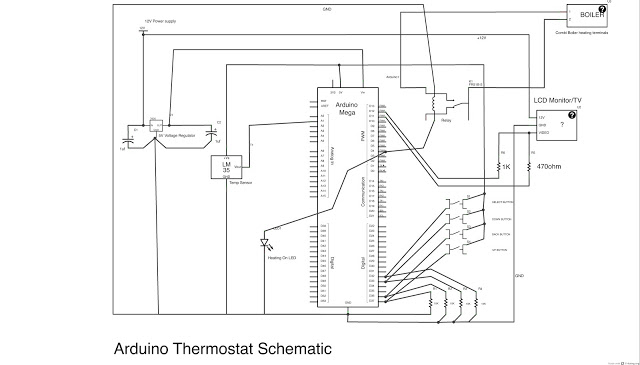
This post outlines the steps taken to build an Arduino-based thermostat, as demonstrated in accompanying videos. The first video showcases a preliminary version of the menu system, providing an overview of the features. The second video presents the completed...
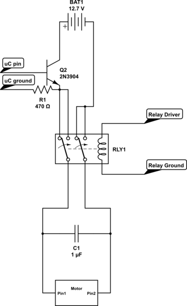
Control the state (on/off) and direction of two linear actuators that are essentially DC motors. The linear actuators operate at 12VDC and draw 10 amps of current at full load. A 25A external power supply has been purchased, as...
A large mirror is installed on the left wall, enhancing the brightness of the room. However, when watching movies, a dark environment is preferred, as reflections of the film appear in the mirror, which can be distracting. To address...
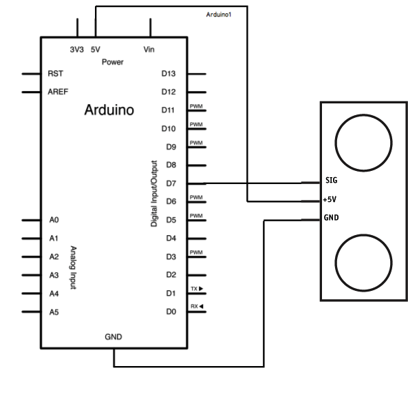
The Ping is an ultrasonic range finder from Parallax. It detects the distance of the closest object in front of the sensor (from 2 cm up to 3 meters). It operates by emitting a burst of ultrasound and listening...
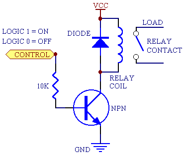
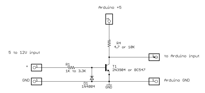
A 5V power supply is used to function as a switch controlled by an Arduino. Direct control from the Arduino pin is not feasible because most general-purpose relays require a minimum of 150mW to activate, which translates to over...

Have you ever wanted your home entertainment or sound system to power on automatically when plugging in your iPod or another portable MP3 player? To achieve automatic power activation of a home entertainment system when a portable device is...