
Build a fully featured Arduino Thermostat

The Arduino-based thermostat is designed to monitor and control the temperature within a specified environment, enhancing energy efficiency and user comfort. The system utilizes an Arduino microcontroller as the central processing unit, interfacing with various sensors and actuators.
Key components of the circuit include a temperature sensor, such as the DS18B20 or DHT22, which provides real-time temperature data to the Arduino. The data from the sensor is processed to determine whether heating is required based on user-defined temperature thresholds. An LCD display or an OLED screen is integrated into the system to visually present the current temperature, set points, and additional information such as the Total Heat Time counter.
For user interaction, a menu system is implemented using a combination of buttons or a rotary encoder, allowing users to adjust temperature settings and view historical data. The line graph feature is achieved through graphical programming libraries that enable the display of temperature trends over the past 24 hours, providing insights into the heating system's performance.
The thermostat is powered using a regulated power supply, ensuring stable operation. The circuit design includes appropriate resistors and capacitors to filter noise and stabilize the readings from the temperature sensor. Additionally, safety features such as over-temperature protection and a relay module for controlling heating elements are incorporated to prevent system failures.
Overall, the Arduino-based thermostat represents an effective and flexible solution for home temperature management, with the capability to adapt to user preferences and provide detailed feedback on heating efficiency.In this post I will attempt to describe the steps I took to build the arduino based thermostat shown in the following videos. The first video was taken when around just half of the coding of the menu system was complete, but gives you a basic run through of the features.
This second video shows the completed thermostat with additional features imp lemented over the holidays, which includes a Total Heat Time counter, and a line graphing feature which shows temperature variations over a 24 hour period, including when the heating was turned on, so from the graph you could see how long it takes your heating system to bring the house up to the desired temperature. 🔗 External reference
Related Circuits
A significant amount of extra hours has been dedicated to work in anticipation of an editing deadline. Despite this, it is deemed appropriate to attempt some hardware hacking. An interest in electronics has existed since before the advent of...
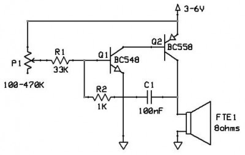
This circuit functions as an oscillator, capable of generating a sound wave or tone. The frequency of the tone, whether high or low, is adjustable via a variable resistor. The volume produced by this circuit is substantial; therefore, it...
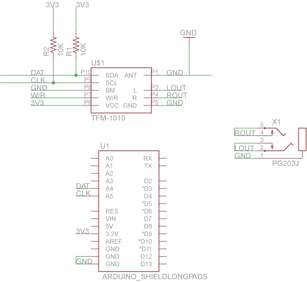
This guide will demonstrate how to construct a custom FM radio receiver shield compatible with an Arduino board. The radio chip utilized in this project is the AR1010, which can be sourced from Sparkfun or Electrokit. Code for initializing...
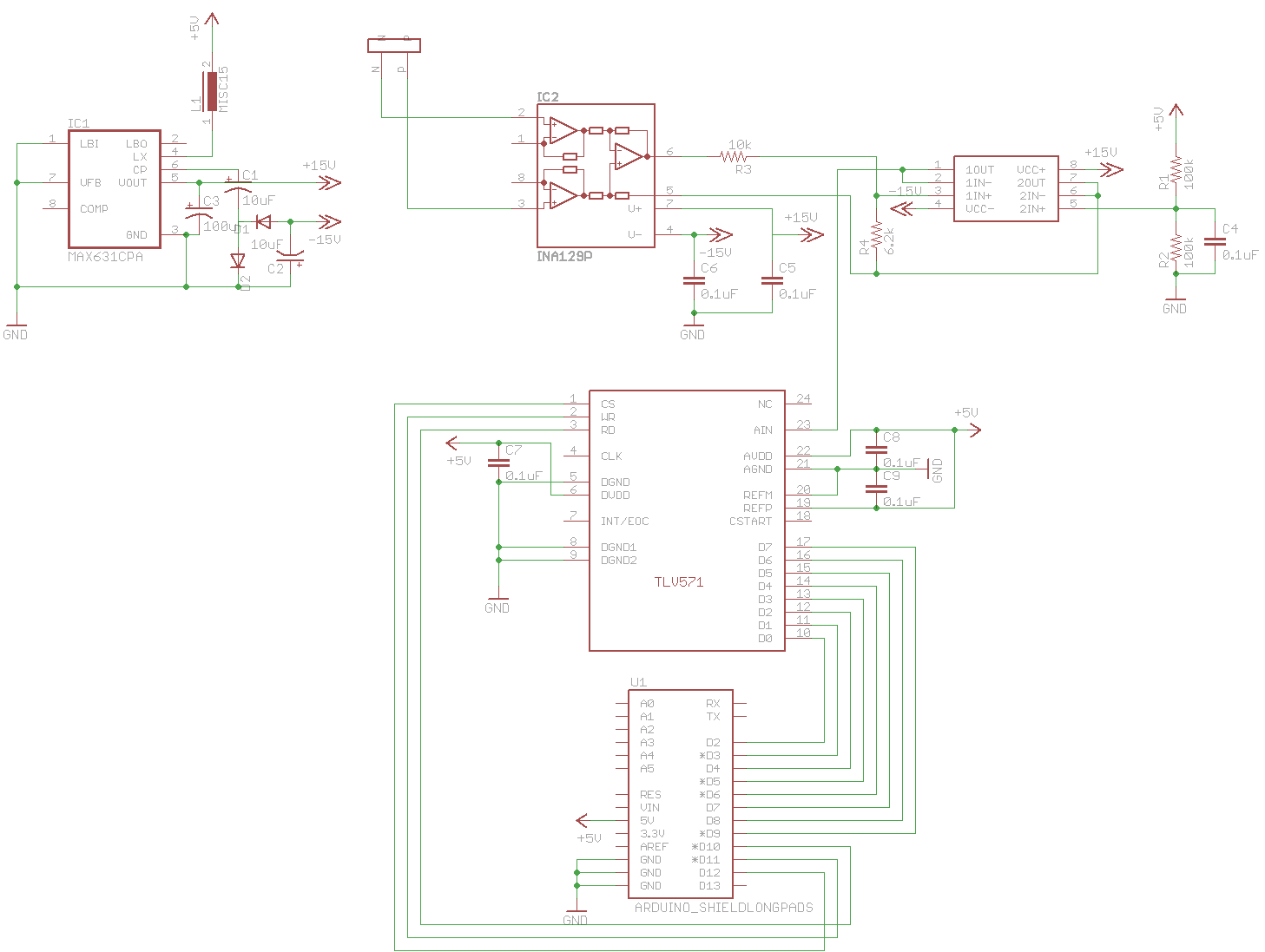
A digital oscilloscope is being developed using Arduino, designed as an Arduino Shield. The current implementation functions but exhibits signal distortions. A TLV571 chip is utilized in the design. The project involves creating a digital oscilloscope that can be mounted...
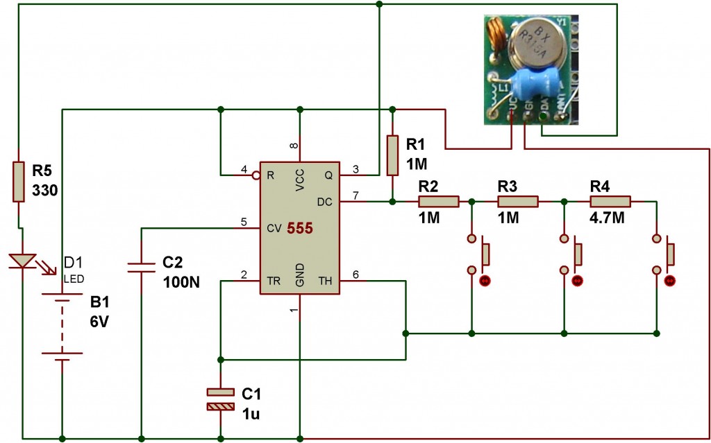
This wireless transmitter and receiver pair operates at 315 MHz. They can easily fit into a breadboard and work well with microcontrollers to create a simple wireless data link. As these are only transmitters, they will only facilitate one-way...
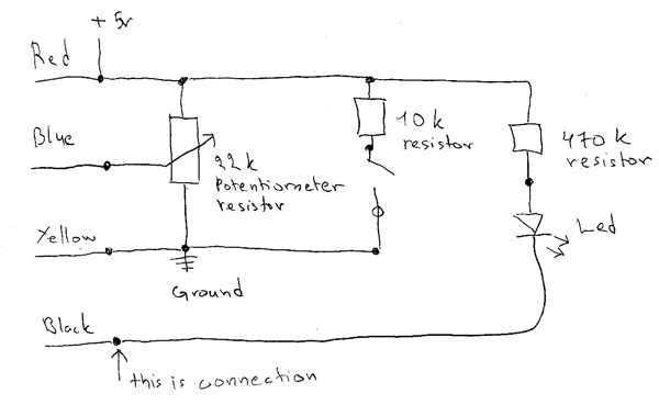
The circuit consists of a 10 kΩ resistor, a 470 kΩ resistor, a potentiometer, and an LED. This circuit is intended for learning Arduino programming in class. The circuit utilizes a combination of resistors and an LED to create...