
Stand-alone Arduino

The video switcher project aims to facilitate the selection and routing of video signals through a user-friendly interface. The design incorporates a USB-to-serial communication method, allowing for compatibility with modern computing devices. The ATmega328 microcontroller serves as the central processing unit, executing control commands based on the digital inputs received from the user interface.
The schematic for this project includes the ATmega328 connected to the USB-to-serial converter, which is responsible for translating USB signals into serial communication that the microcontroller can interpret. The microcontroller is powered via the 5-volt supply from the USB port, ensuring that it operates efficiently without the need for additional power sources.
In terms of layout, careful attention must be paid to the placement of the USB-to-serial converter, ensuring that signal integrity is maintained while minimizing noise. The use of decoupling capacitors near the power supply pins of the ATmega328 helps stabilize the voltage levels during operation. The DTR line from the USB-to-serial converter is crucial for the auto-reset feature, allowing for seamless uploading of new firmware without manual intervention.
The finalized PCB design will also consider the size constraints imposed by the chosen components, ensuring that the layout is compact yet functional. The inclusion of headers for programming and debugging purposes will facilitate future modifications and troubleshooting. Overall, this project exemplifies the integration of modern microcontroller technology with traditional video switching applications, providing a robust solution for video signal management in various environments.A Video Switcher which can be controlled using the computer`s parallel port. Unfortunately, fewer PCs are fitted with parallel pors these days and, for a laptop, it`s not really an option so the need to control the Switcher through a USB port became important. The Video Switcher only needs three digital inputs so, although the PICAXE range of Microcontrollers would probably
provide a chip with a more economical use of pins, the Arduino seems easier to interface with a standard USB cable and it`s a useful enough project to justify building a cut down stand-alone Arduino. A stand-alone Arduino can conveniently be divided into two parts: The ATMega328 with its associated support components and the USB-to-Serial interface needed to upload sketches and provide the serial communication that was to replace the parallel port.
I`d decided from the outset to use an ATmega328 with the Arduino bootloader already programmed in and not to complicate things by using a `blank` chip. I bought the pre-programmed ATmega328 and the other components from HobbyTronics as they`re based relatively locally to me (in the UK at least!).
The 328 has a convenient pinout label already attached! The USB to Serial converter supplies 5 volts to the Arduino from the computer`s USB socket. There are several different USB to Serial converters available, all of which do more or less the same job. I found the Sparkfun Breakout Board for FT232RL (shown to the right) a bit fiddly to handle and it was necessary to desolder the 3.
3 volt solder bridge and bridge the 5 volt pads instead. It`s shown on the schematic but is a bit hard to spot unless you`re aware of it. It`s also necessary to solder the two 9-way male header strips to the board. I used a BV104 breakout board made by ByVac (shown above) which is described as a "Silicon Labs Low Cost USB to serial bridge". It comes with the two 4-way male headers already attached and works out about 2. 50 UKP cheaper than Sparkfun`s. It`s also only about 2/3rds the size of the Sparkfun board which is useful if space is a problem. One slight consideration with the BV104 is that, although its chip has an internal 3. 3 volt regulator for its own supply (and is made available on a header pin - max 100mA), the 5 volts which will supply the Arduino comes straight from the computer`s USB socket and, therefore, the BV104 offers no additional protection.
I fitted the two rows of female sockets which you can see in the photo (above left) because, during development, I wanted access to the standard serial signal lines - especially the DTR connection to provide optional "Auto Reset" for the ATMega328 when uploading sketches (the green "fly lead" in the photos). It`s not necessary to fit these sockets in the finalized PCB version of the DIY Arduino. The auto-reset can cause some problems by initiating a reset when you connect other USB devices to the same USB Hub - hence the flying lead.
The finalized stand-alone Arduino PCB will use a header and jumper to disconnect the auto-reset once a sketch is uploaded. I`m running Windows 7 (64-bit) and was pleasantly surprized to discover that both the Sparkfun board and the ByVac board were recognised by the Operating System and drivers were installed automatically.
The Sparkfun board`s driver shows FTDI as the manufacturer and the ByVac board shows up as "Silicon Labs CP210x USB to UART Bridge". When I tried the finished project on my laptop, which runs XP, XP did what it does best and complained about the missing drivers.
Feeling a bit lazy (or lucky), I asked it to search on the internet for suitable drivers and, to my amazement, it successfully located and installed the correct Silicon Labs driver! Meanwhile, back at the breadboard stage, having tested the circuit successfully on the breadboard, it was time to get designing the final printed circuit board.
🔗 External reference
Related Circuits
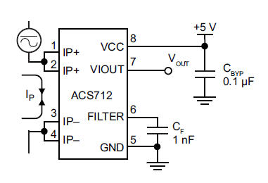
The primary component utilized is the ACS712 sensor from Allegro MicroSystems, designed for measuring current. It offers cost-effective and accurate solutions for AC or DC current sensing in industrial, commercial, and communication systems. A precise, low-offset, linear Hall sensor...
Controlling higher-power devices such as lights, motors, pumps, and doors with an Arduino can be both fascinating and practical. However, managing power line voltages presents challenges and potential hazards. There are essential differences between controlling AC and DC power,...
The device is designed to promote respectful time management during meetings, particularly useful in ship-room or SCRUM meetings. The following is a list of components required, including links for purchasing specific parts. It is advisable to check eBay or...
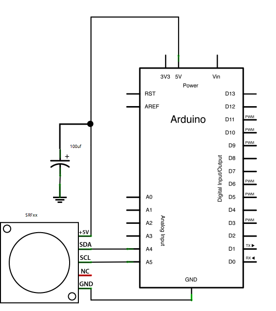
This example demonstrates how to read a Devantech SRFxx, an ultrasonic range finder that communicates via the I2C synchronous serial protocol, using Arduino's Wire Library. The I2C protocol utilizes two wires for data transmission: a serial clock pin (SCL)...
This evening, after returning home from a paragliding appointment, there was a realization that the RGB LED driver code written the previous day needed improvement. The code was refined and annotated extensively for educational purposes. Although the current skill...
This document explains how to utilize an Arduino to control up to 12 servos simultaneously with minimal jitter. A straightforward serial interface allows for the control of the position of these 12 servo channels. Additionally, it is possible to...