
Barebones Arduino

This project involves creating a minimalist Arduino setup on a breadboard, which is an excellent approach for prototyping and learning about microcontroller applications. The ATmega168 microcontroller serves as the heart of the circuit, where it executes the programmed instructions. The 1kΩ resistor is typically used for current limiting, particularly in conjunction with the button, which can be configured as an input to trigger specific functions in the microcontroller.
The two 22pF capacitors are essential for stabilizing the oscillator circuit connected to the 16MHz crystal, ensuring accurate clock signals for the microcontroller operation. The two 10µF capacitors are used for decoupling, providing stability to the power supply by filtering out noise and voltage spikes that could affect the performance of the microcontroller.
A 5V voltage regulator is included to ensure that the microcontroller receives a stable voltage supply, which is crucial for reliable operation. The power source should be at least 7 volts to ensure proper regulation down to the required 5 volts, taking into account the dropout voltage of the regulator.
For programming, the microcontroller can be loaded with code either through a USB-Serial breakout board, which allows for direct USB communication, or by using another Arduino board configured as an in-system programmer (ISP). Once programmed, the chip can be placed into the breadboard circuit, ready to execute the intended applications.
This setup is particularly beneficial for hobbyists and educators who wish to understand the fundamentals of microcontroller programming and circuit design without the complexities of standard Arduino boards.You can easily build a barebones Arduino yourself. This project shows a breadboarded Arduino without an FTDI chip. This means no USB connectivity (this could be however accomplished using a USB-Serial breakout board). Use an ATMEGA168, a 1k resistor, a button, two 22pF Capacitor, two 10 µF Capacitor, 5V Voltage Regulator, and a 16MHz clock crys
tal. You could program the chip with a USB-Serial breakout board or you could program the chip with an Arduino board and then pop it in the circuit. The power source should be at least 7 volts (we don`t have that part yet). 🔗 External reference
Related Circuits
A straightforward project involves using an Arduino to rotate a GH-2 camera on a fluid head by specified degrees to capture 360-degree panoramas. The motor control is uncomplicated, and there is a wealth of DIY motor projects available. Assistance...
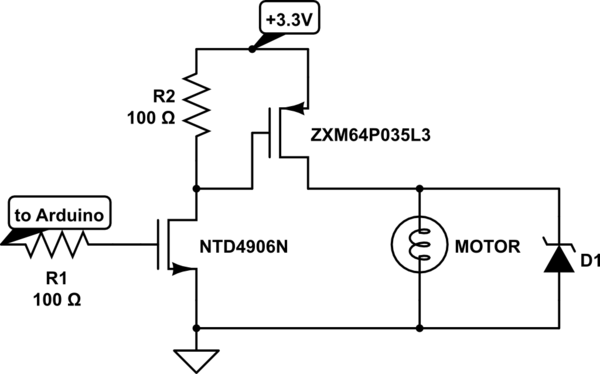
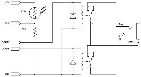
Charge a simple servo that only has + and - pins. Typically, the - pin is connected to ground, while the + pin is connected to a digital output from an Arduino. This setup works, but the servo operates...
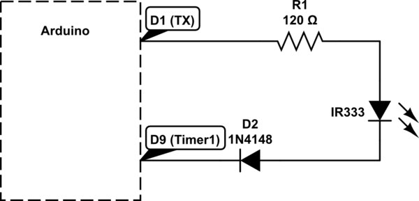
Utilizing a digital infrared (IR) receiver module and a digital IR transmitter module, each connected to separate Arduino Uno boards, the objective is to transmit data, such as "1234", to the receiver and display this data on an LCD....
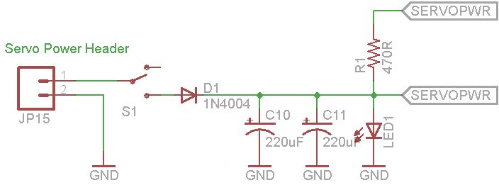
This document explains how to utilize an Arduino to control up to 12 servos simultaneously with minimal jitter. A straightforward serial interface allows for the control of the position of these 12 servo channels. Additionally, it is possible to...
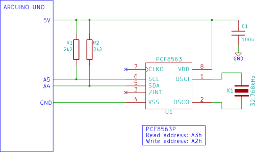
The Arduino displays the time and date on an optional LCD and in the Arduino IDE serial monitor window. A PCF8563 real-time clock (RTC) integrated circuit (IC) is utilized to generate the time and date. The time and date...
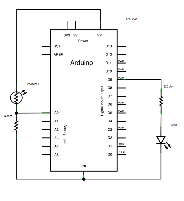
This example demonstrates a technique for calibrating sensor input. The Arduino takes sensor readings for five seconds during startup and tracks the highest and lowest values obtained. These sensor readings during the first five seconds of the sketch execution...