
Assembling The Speed Controller
The assembly of the H-bridge board involves careful attention to component orientation and handling techniques to avoid damage to sensitive parts. The polarized components, including tantalum capacitors and zener diodes, must be installed with their marked leads correctly aligned to ensure proper functionality. The integrated circuit sockets are designed to facilitate easy installation of the ICs, with notches that align with the silkscreen markings on the board.
When soldering, it is critical to avoid excessive heat exposure to heat-sensitive components like zener diodes and MOSFETs. Techniques such as timing the soldering duration and allowing components to cool can prevent damage. The assembly process is structured to minimize tilting of the board by installing components of equal height simultaneously, enhancing stability during assembly.
The use of notation for component placement simplifies the installation process, allowing for clear identification of locations on the board. Each component's position is designated with a combination of letters and numbers, aiding in precise placement. Following the outlined steps systematically ensures a successful assembly of the H-bridge board, leading to a functional circuit capable of driving motors or other loads efficiently. Proper assembly techniques, orientation checks, and careful soldering practices contribute to a reliable and robust electronic design.The. 01uf monolithic capacitors will be marked `103 K` and the 15pf monolithic capacitors are marked `15 J`. It is very important that you don`t confuse the two. DO NOT take either the MOSFETs or the Integrated circuits off their protective static containers until just before you use them.
Ideally, you should also keep yourself grounded whenever you handle static sensitive parts. In general it is sufficient to touch something that is grounded before you pick up a part. Some of the items in the kit are polarized. This means that they must be installed with the correct orientation. The parts that are polarized are the tantalum capacitors (marked with a + on one lead), the zener diodes (marked with a band on one end), one of the two resistor packs (marked with a dot on the end) and the integrated circuits. When you install the integrated circuit sockets be sure and orient the socket correctly (line up the notch shape with the silkscreen) so that it will guide you when installing the ICs.
The zener diodes and the MOSFETs are heat sensitive. This means that if you hold the soldering iron on them too long you can damage them. My reccommendation is that you count "one one thousand, two one thousand, etc" and if you get to "seven one thousand" and you haven`t successfully created the joint you stop. Wait 10 or 20 seconds for the part to cool and try again. This is particularly difficult on the areas where there are really wide traces because the copper foil absorbs the heat.
The following steps will take you through the assembly of the H-bridge board. Read through all of the steps first, then follow them in order when you assemble the board. The assembly steps attempt to build up the board by "levels", that is putting equal height components in at the same time so that the board doesn`t rock and tilt on your work surface while building it. On some of the steps you will see a warning sign, this sign indicates that the components being installed in that step must be installed in a specific orientation.
Below is a picture of the unpopulated H-bridge board. The board is bordered by a sequence of letters and numbers. The letters and numbers are used to identify specific locations on the board using a notation of the form B, 3. This location would be column B, row 3 on the board. Similarly the location B, 1. 5 would be column B, between rows 1 and 2. Whereas the location B, 2-4 indicates a location in column B that spans rows 2, 3, and 4. Locate the H-bridge board, its shown above in figure 1, and install the two IC sockets (8 pin and 16 pin) and the 8 pin SIP socket.
Note that the IC sockets have a notch that should line up with the silkscreen notch. Turn the board over and solder them. I find a bit of tape (masking tape) will hold them to the board while I`m flipping it over. Locate the two zener diodes and install them. They are located at positions D, 3 and D, 4 in the image above. Watch the orientation to make sure the band faces to the "left" (away from the screw connectors. ) Note that the Zeners may be marked 1N5242 or 1N4742 Install the 100K resistor pack at location C, 2-3. Watch the orientation of the resistor pack. The pin one "dot" or "line" indication should face away from the 8 pin socket which is pointed down in the image above.
Install the 1uF tantalum at location B, 1. 5. Watch the orientation of the tantalum, the plus marked pin goes in the hole marked "+". The positive hole is the upper hole. Install the four MOSFETs at locations D, 1, D, 2, D, 3, and D, 4, and solder them carefully. Watch the orientation of the MOSFETs. The tabs on the MOSFETs sho 🔗 External reference
Related Circuits
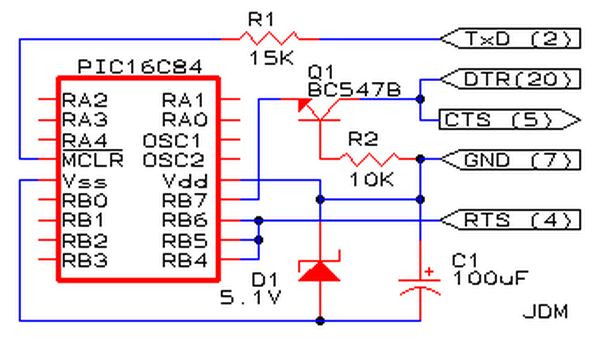
Affordable PIC Programmer. This programmer is compatible solely with the PIC16F84 microcontroller. It is reliable, as it rarely encounters errors, and functions well with nearly all computer systems, in contrast to some alternatives. The PIC programmer designed for the PIC16F84...
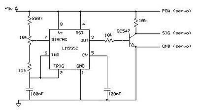
This circuit enables the testing of a servo motor. The angle of the servo can be adjusted using a 10k potentiometer. It is possible that not all positions can be achieved with this circuit; experimenting with different resistors may...
The following circuit illustrates a simple stepper motor controller circuit diagram. This circuit is based on the 7404 integrated circuit. Features include suitable heat dissipation. The simple stepper motor controller circuit utilizes the 7404 hex inverter IC to control the...
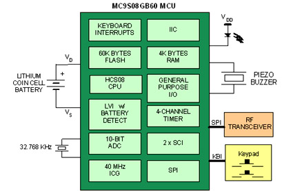
Battery-powered devices, such as electric toothbrushes, shavers, cell phones, PDAs, MP3 players, and remote controls, are integral to daily life. Consequently, power management has become a critical consideration for embedded designers. Microcontrollers (MCUs) provide various methods for managing power...
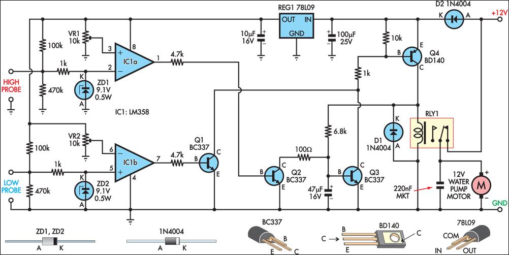
This circuit operates an automotive windscreen washer pump to fill a 20-litre drum from a 205-litre water reservoir. The drum is suspended above a drip line, which irrigates a vegetable garden. Two stainless steel probes mounted in the drum...
It can safely charge a 7-cell RC2000 pack in about 14 minutes, and an RC2400 or CP2400SCR pack in about 17 minutes. As a NiCd cell is being charged, two things happen which affect its temperature. Due to resistive...
Warning: include(partials/cookie-banner.php): Failed to open stream: Permission denied in /var/www/html/nextgr/view-circuit.php on line 713
Warning: include(): Failed opening 'partials/cookie-banner.php' for inclusion (include_path='.:/usr/share/php') in /var/www/html/nextgr/view-circuit.php on line 713