
astable multivibrator

In a typical electronic circuit designed for blinking an LED or similar output device, the timing characteristics are often governed by resistor-capacitor (RC) timing circuits. In this scenario, the use of two 47k ohm resistors allows for adjustments in the timing of the blinking effect. The resistance values can be varied from 22k ohm to 100k ohm, providing flexibility in the circuit's response time.
When the resistance increases, the time constant of the circuit also increases, which leads to a longer delay between each blink of the LED. This is due to the relationship defined by the RC time constant formula, τ = R × C, where τ is the time constant, R is the resistance, and C is the capacitance. In this case, the choice of capacitors in conjunction with the resistors will determine the overall blinking frequency.
For instance, if a capacitor of 10µF is used in conjunction with the two 47k ohm resistors, the time constant can be calculated as follows:
τ = 47,000 ohms × 10 × 10^-6 farads = 0.47 seconds.
This indicates that the LED would take approximately 0.47 seconds to charge and discharge, resulting in a blinking interval that can be perceived by the human eye. By substituting the resistors with higher values, such as 100k ohm, the time constant will increase, leading to slower blinking rates. Conversely, using lower resistance values will yield a faster blinking rate.
In summary, the selection of resistor values in this circuit plays a crucial role in determining the timing of the blinking output, allowing for customization based on desired visual effects or functional requirements.* 2 x 47k ohm resisters anything from 22k to 100k ohm should work. Value of these changes the timing of blinking (larger the value, slower the blinking). 🔗 External reference
Related Circuits
The circuit remains in a stable state until a triggering signal is applied to its input. Upon receiving the triggering signal, the output transitions from a stable state to a quasi-stable state and returns after a specified time period,...
A one-shot multivibrator circuit, commonly referred to as a monostable multivibrator or timer, is designed to generate a pulse strobe of fixed duration in response to an input trigger. The one-shot multivibrator is a fundamental circuit used in various electronic...
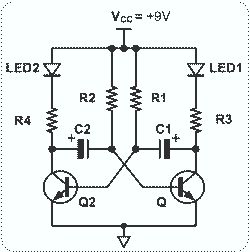
This circuit is straightforward and easy to construct, utilizing two transistors as active components along with several passive components such as resistors, capacitors, and two LEDs. The circuit employs the MPS2222 transistor, though any NPN type transistor can be...
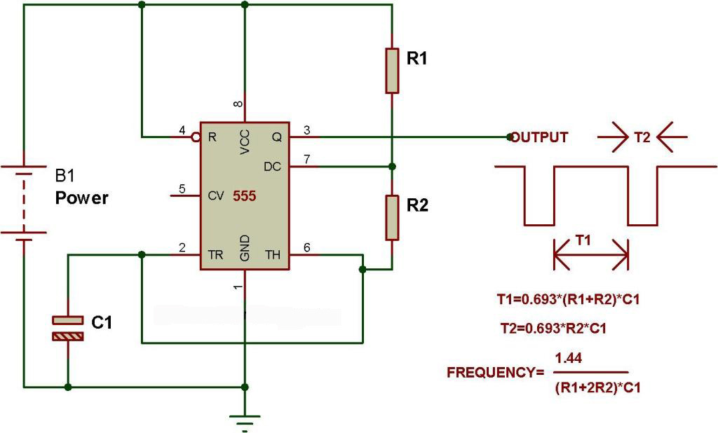
The schematic presented originates from buildcircuit.com. This circuit functions as a music generator, infrared transmitter, and LED blinker, depending on the values of R1, R2, and C1. A minor modification to the previous circuit allows it to operate as...
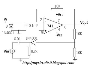
In this circuit, a standard operational amplifier (op-amp) is configured as an astable multivibrator. The output is non-symmetrical, but it has the advantage of being controlled by only one resistor and one capacitor: a 100k variable resistor (U2) and...
This is a versatile discrete monostable circuit. The circuit consists of a 2N3819 JFET and 2N3704 transistors. This monostable multivibrator circuit has an additional input to enable or inhibit the function at any time without causing an output pulse....