
astable multivibrator

The described circuit operates as a relaxation oscillator, utilizing a capacitor and resistors to generate oscillations. The charging and discharging of the capacitor C through resistors R1 and R2 create a timing cycle that is crucial for the oscillator's frequency output.
In this configuration, the capacitor charges towards the supply voltage, and the voltage levels are monitored by two comparator pins (pin 6 and pin 2). The thresholds for triggering the state changes of pin 7 are set at 2/3 and 1/3 of the supply voltage, respectively. This hysteresis ensures stable operation without false triggering due to noise.
The resistors R1 and R2 play essential roles in determining the charge and discharge rates of the capacitor, directly influencing the frequency of oscillation. The logarithmic scales provided in the graph assist in visualizing the relationship between resistance values and frequency output, allowing for easier calculations and adjustments in circuit design.
The frequency can be calculated using the formula derived from the time constants associated with the charging and discharging cycles. The approximate frequencies of 900Hz and 9Hz correspond to specific resistor values (21k and 210k) and are indicative of the circuit's versatility in generating different frequencies based on component selection.
This oscillator design is commonly used in various applications, including timers, pulse generation, and tone generation in audio circuits, demonstrating its utility in electronic systems.The capacitor C charges via R1 and R2 and when the voltage on the capacitor reaches 2/3 of the supply, pin 6 detects this and pin 7 connects to 0v. The capacitor discharges through R2 until its voltage is 1/3 of the supply and pin 2 detects this and turns off pin 7 to repeat the cycle.
The scales on the graph are logarithmic so that 21k is approxi mately near the "1" on the 10k. Draw a line parallel to the lines on the graph and where it crosses the 0. 1u line, is the answer. The result is approx 900Hz. The scales on the graph are logarithmic so that 210k is approximately near the first "0" on the 100k. Draw a line parallel to the lines on the graph and where it crosses the 1u line, is the answer. The result is approx 9Hz. 🔗 External reference
Related Circuits
An astable multivibrator, also known as an oscillator circuit, operates on the principle of positive feedback. This type of circuit can be constructed using operational amplifiers, logic gates, or transistors. An astable multivibrator is a fundamental electronic circuit that generates...
The schematic for a monostable multivibrator is shown in figure 3-11. Like the astable multivibrator, one transistor conducts and the other cuts off when the circuit is energized. More: Recall that when the astable multivibrator was first energized, it...
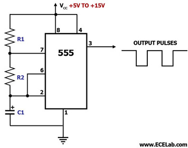
This circuit diagram illustrates the configuration of a 555 timer integrated circuit (IC) as an astable multivibrator. An astable multivibrator is a timing circuit characterized by unstable 'low' and 'high' states. Consequently, the output of an astable multivibrator continuously...
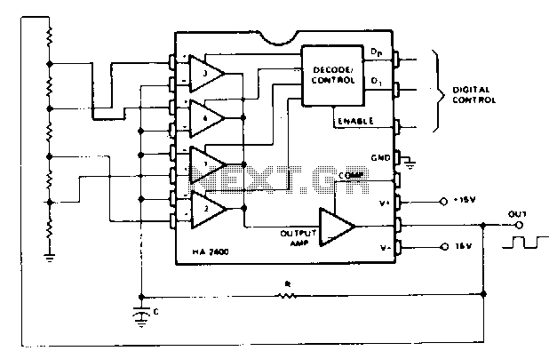
This is the simplest programmable oscillator circuit, requiring only one stable timing capacitor. The output square wave has a peak-to-peak voltage of approximately 25 V, with rise and fall times of about 0.5 µs. Additionally, if a programmable attenuator...
A monostable multivibrator is exemplified by the pulse detector within flip-flop circuitry, which briefly enables the latch portion during clock signal transitions. This device is classified as monostable due to its single stable state, which can maintain its output...

A multivibrator is an electronic circuit that implements various simple two-state systems, such as oscillators, timers, and flip-flops. The most common type is the astable multivibrator, which continuously oscillates between two states, generating a square wave. Another type is...