
Astable Multivibrator with 2 Transistors
This circuit employs two NPN transistors, typically the MPS2222, to create a simple oscillator or switching circuit. The configuration allows for the generation of square wave signals, effectively transitioning between HIGH and LOW states.
The circuit operates with a power supply of 9V, ensuring the Emitter-Base Voltage remains below the maximum threshold of 5V for reliable operation. The use of capacitors C1 and C2 in conjunction with resistors R1 and R2 is critical for establishing the timing characteristics of the circuit. The time constant, defined as \( t = 0.693 RC \), is pivotal in determining the duration of the HIGH and LOW states, where R represents the resistance in ohms and C represents the capacitance in farads.
The output of the circuit is indicated by two LEDs, which serve as visual indicators of the state of the circuit. Current limiting resistors are incorporated to prevent excessive current from flowing through the LEDs, thereby protecting them from damage. The design allows for the output to toggle between HIGH and LOW, creating a pulsing effect that can be utilized in various applications, such as blinking lights or signal generation.
The frequency of the output signal can be calculated based on the time period derived from the time constant. The transition frequency from HIGH to LOW can be computed using the formula \( f = \frac{1}{T} \), where \( T \) is the period of the oscillation. This frequency is determined by the values of the resistors and capacitors used in the circuit, allowing for customization based on desired operational parameters.
Overall, this circuit exemplifies a fundamental application of transistor switching, providing a basis for more complex electronic designs.This circuit is basically simple and easy to build, it uses two transistors as active components and a few passive components like resistors, capacitors and two LEDs. The circuit makes use of the MPS2222 transistor. You can use any NPN type transistor as the basis of your circuit provided that, the transistors Emitter-Base Voltage is less than 12V and has a maximum value of 5V.
This is to ensure that the circuit will work under a 9V Battery power supply. The circuit generates a H(HIGH) to L(LOW) level and L to H level transition. This H to L or L to H transition is generated by capacitors C1 and C2 and resistors R1 and R2, the LEDs acts as output loads to the circuit and the other resistors serves as current limiting resistors for the protection of the LED diodes. Taking one-half of the circuit we can calculate the time period which makes the high or low transitions for a single transistor.
Thus, the time constant can be calculated as: t = 0.693 RC The transition frequency from HIGH to LOW state can be computed as: 🔗 External reference
Related Circuits
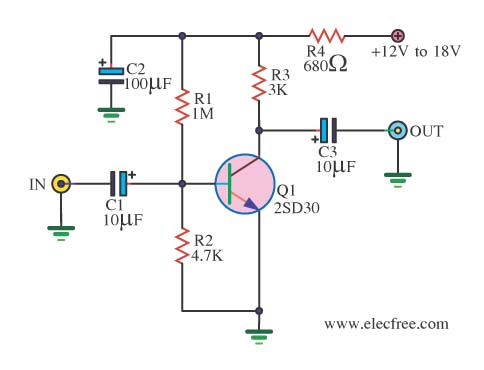
When there is a need to amplify audio signals from various sources before they reach a custom amplifier, a preamplifier (or preamp) is typically employed. This document suggests a specific circuit that is interesting due to its use of...
There are many who built the Easy Programmer or C-52 Evaluation Board, asking for the RS232C level converter chip, DS275. Many have changed to MAX232 instead, because it is not available in their home. Here is another simple and...
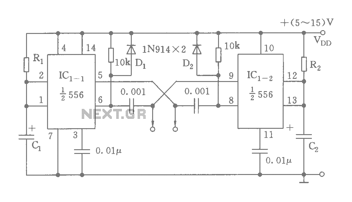
The circuit features a dual time base using a 556 timer, which comprises two synchronized multivibrators and two output clock signals. The output signals are synchronized with defined intervals, and the oscillation frequency can be adjusted by varying the...
The schematic for a monostable multivibrator is shown in figure 3-11. Like the astable multivibrator, one transistor conducts and the other cuts off when the circuit is energized. More: Recall that when the astable multivibrator was first energized, it...
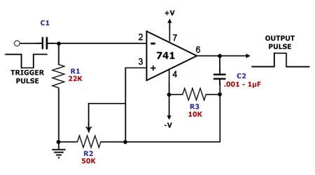
This is a monostable multivibrator circuit that utilizes a single operational amplifier. The primary component of this circuit is the 741, a general-purpose operational amplifier. A monostable multivibrator is a timing circuit that changes its output state when triggered...
The MC74HC04 IC is a low cost CMOS Hex Inverter. I used this type mainly because, it is what I have, although you can use LS type but, with a little modification or exemptions. More: For 'HC' type: Always...