
please 555 circuit
A circuit design utilizing a 555 timer for controlling an LED array can be implemented to achieve the desired pulsing effect. The 555 timer operates in astable mode, generating a square wave output that can drive the LED array. The essential components include the 555 timer IC, resistors (R1 and R2), a timing capacitor (C1), and the LED array.
In this configuration, R1 and R2 establish the frequency of the oscillation, while C1 determines the duration of the high and low states. To achieve a pulsing effect, it is recommended that R2 be a variable resistor (potentiometer), allowing for frequency adjustments. The formula for the frequency (f) of the output signal is given by:
f = 1.44 / ((R1 + 2 * R2) * C1)
The output from pin 3 of the 555 timer can be connected to the base of a transistor, which acts as a switch to control the LED array. A current-limiting resistor may be necessary to protect the LEDs from excessive current, which could lead to overheating or damage. The transistor should be chosen based on the current requirements of the LED array, ensuring it can handle the load without exceeding its ratings.
The capacitor (C1) should be selected based on the desired blinking frequency. For instance, to achieve a pulsing effect at 10Hz, appropriate values for R1, R2, and C1 must be calculated. The use of a larger capacitance value will result in a slower blinking rate, while smaller values will increase the frequency.
It is important to ensure that the connections are made correctly, with the timing capacitor connected between pin 6 and ground and the resistors connected to pins 7 and 6. Pin 2 should be connected to pin 6 to allow for feedback, ensuring the timer oscillates properly. The output from pin 3 will drive the LED array through the transistor, which should be connected to a suitable power supply, ensuring that the voltage levels are within the operational range of the components used.
Lastly, it is advisable to verify all connections and component values before powering the circuit to prevent damage to the components, particularly the 555 timer and the LED array. Proper testing with a multimeter can help confirm that the circuit operates as intended, providing the desired pulsing effect for the night vision camera application.I got frustrated and decided to hook it up to a 15v supply and jump R3 with a clip-on soldering heat sink. 555`s smell great when you fry`em. I have about 9 more tries before I run out of parts, but for now I will seek help in the forums and stick to the simulator.
The IR array is rated at 920+nm but I bought them from china and they have plenty o f visible light. I have been using a volt meter, and the array isn`t getting enough voltage, (. 5V out of the 2nd transistor) but just in case, I am using an IR sensitive camera as well. I am in a hurry and have to go to work now, but I will have more voltages later. I don`t quite remember them all. I think that pin three on the 555 the voltage was okay, but after R3 It had only. 5v and the transistors weren`t doing much. Could it be that my 48LED arrays are too power hungry or something I have looked up other examples of timing circuits with the 555 for the simulator I have (Yenka) and it seems that all of them have the controlling resistor where I have R2 and not R1, and what`s with the funny loop on R1 I know that to get a reading on the resistance, It`s the middle pin and one of the ends, but it seems to be completely bypassed when I have it all hooked up and there is no resistance between pin 3 and 1. BUT THE LIGHT SHOULD STILL COME ON RIGHT It only came on once on my first model, and stayed on. Maybe the timing was too slow but the potentiometer did nothing. Like I said, the simulator examples had the variable resistor in another spot. Thanks in advance for any advice. I am fairly new to this stuff. You should put the pot where R2 is. The 555 won`t like it if the pot is set to zero. The loop is hooking pin 1 to pin 2. I don`t know the spec on your LED, but they usually need something to limit the current. Maybe it is built in. No, nothing illegal. I just want an LED array to blink on and off. It`s for a nightvision camera project. I removed the IR filter off of a camera lense and if I have the array "ON" then it`s too intense. I thought it might have a neat effect if I make it pulse at 10Hz, or 60Hz. aiming for syncopation. No, nothing illegal. I just want an LED array to blink on and off. It`s for a nightvision camera project. I removed the IR filter off of a camera lense and if I have the array "ON" then it`s too intense. I thought it might have a neat effect if I make it pulse at 10Hz, or 60Hz. aiming for syncopation. You may be pulsing the lamp ON for too short a period, I would suggest that you operate the lamp directly, use a suitably current rated push button and see how quickly the lamp can be switched ON and OFF.
You should put the pot where R2 is. The 555 won`t like it if the pot is set to zero. The loop is hooking pin 1 to pin 2. I don`t know the spec on your LED, but they usually need something to limit the current. Maybe it is built in. I`ve gone in a lot of circles. I`ve searched for plenty of "how-to`s" on google+youtube for 555 blinking LED array. Some come really close to exactly what I`m looking for and some probably DO have all of the correct answers to my questions but none are exact, none are in order, and none are in my native noob tongue. Lots of schematics show me that there are potentiometers but none are labeled pin1 pin2 pin3. It`s just a picture showing me it exists. Is the middle pin always the wiper Do some have specific polarity Mine are 3006p multi-turn trimmers.
My simulator allows me to turn normal passive linear resistors into pots by assigning a slider to control resistance but none have three pins. I have replaced R1 and R2 with pots in the simulator and added another variable resistor just downstream of r1 before C2 to find out if it does anything.
It doesn`t do anything. So why then would I connect pin 2 back to the 12v if that is my variance Shouldn`t that be connected to pin 7 of the 555 and R2 This is what I was aiming for by adding the third variable resistor in the simulator. Why doesn`t it do anything in the simulator or in practice I think I`m still looking at it all wrong.
Okay so I had it blinking really slow. About 10 seconds on 10 seconds off. Then I realized that I have 47 µF capacitors instead of. 47 µF. So I plugged it into the simulator and sure enough, It blinks slow with 47 µF. It all seemed to do fine in the simulator with. 01 µF ceramic in place of the 47 µF electrolytic. So I swapped it, and plugged it in, and the light came on and stayed on. I set the pot for 98k to give it about 10Hz and nothing happened. Light stayed on then eventually something happened. The light went off and stayed off. 🔗 External reference
Related Circuits
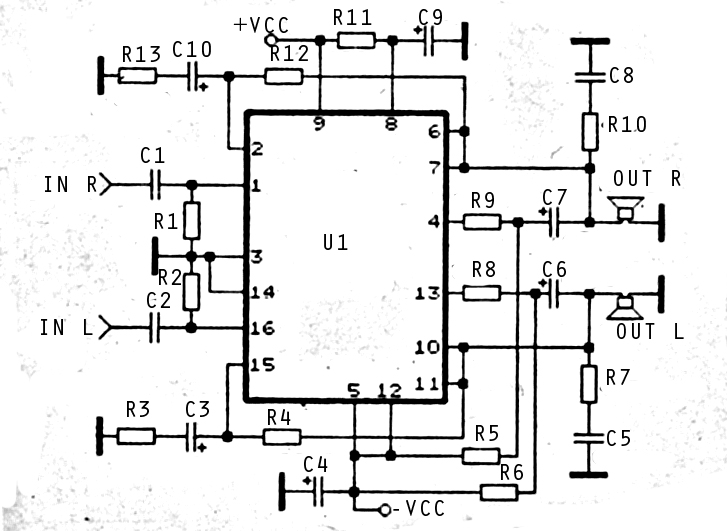
The audio amplifier circuit is highly suitable for home use, particularly with subwoofer or woofer speakers. Commonly referred to as a home amplifier, these audio amplifiers are based on integrated circuits (ICs), specifically the STK series, which includes models...
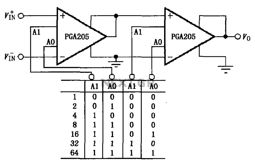
A binary gain step circuit is illustrated using the PGA205, which has a gain range of 1 to 64. The circuit employs two PGA205 devices in cascade, resulting in a total gain that is the product of the individual...
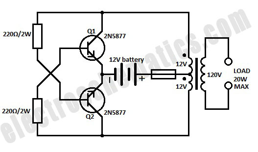
A simple 12-volt inverter circuit. This 120V AC power source is constructed using a basic 120V:24V center-tapped control transformer and four additional components. The circuit generates a clean 200-V peak-to-peak square wave at 60 Hz and is capable of...
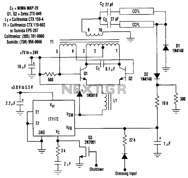
This circuit is a 92%-efficient power supply for cold-cathode fluorescent lamps (CCFLs), which are used to backlight LCDs in portable equipment. The efficiency depends heavily on the component types, particularly C1, Q1, Q2, L1, and T1, whose manufacturers are...
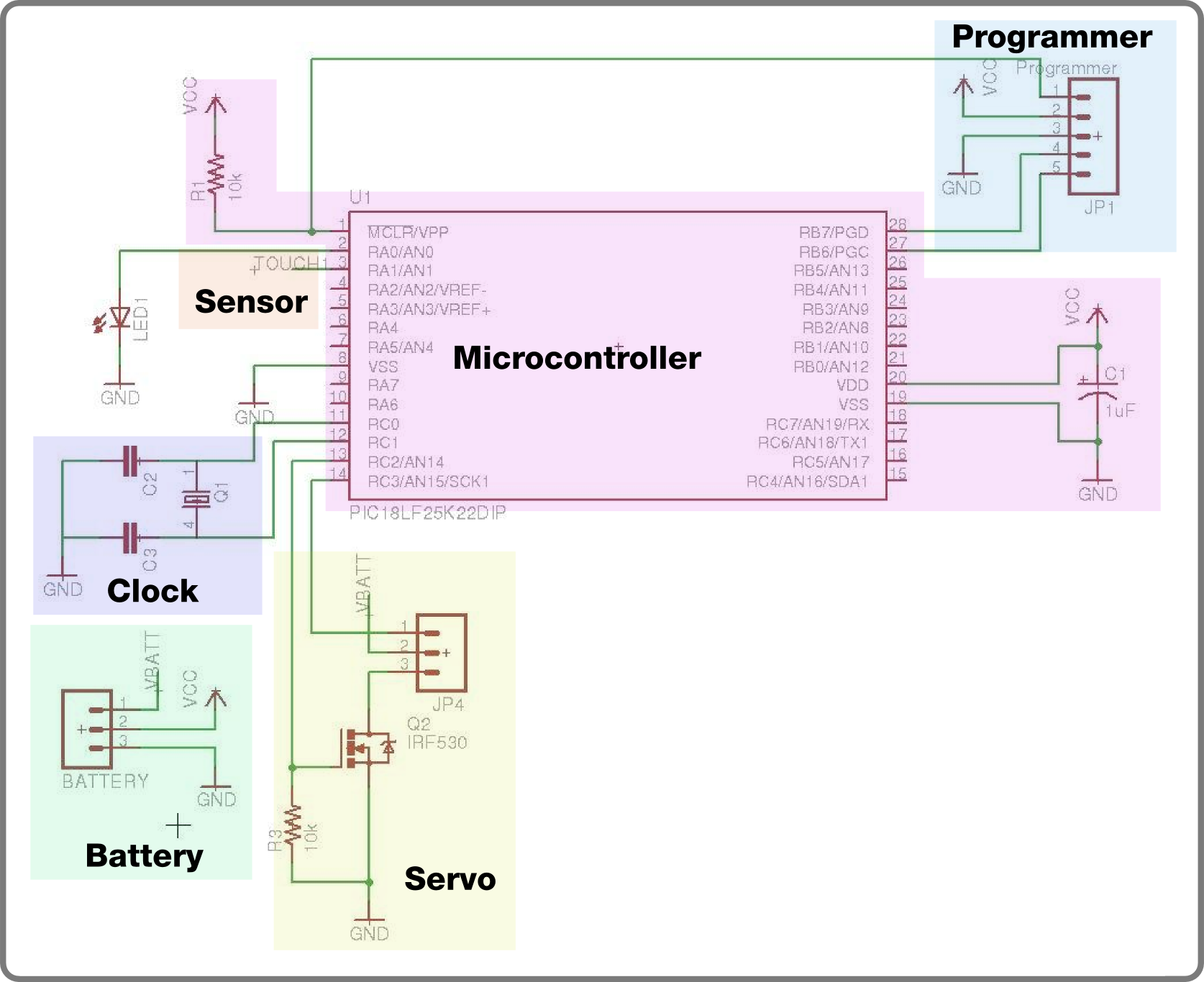
For the second build in the Make It Last Build Series, a robotic plant is being constructed. This week focuses on assembling the control circuit, which will be used in future weeks to animate the plant. The basic circuit...
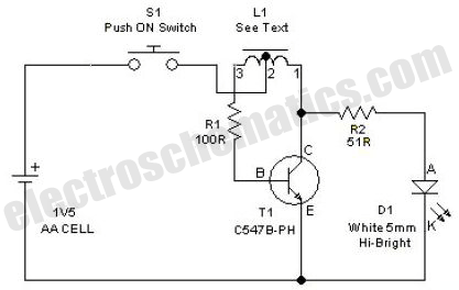
This simple LED driver circuit allows the operation of up to seven LEDs using a single NiMH (Nickel Metal Hydride) AA cell. The circuit generates voltage pulses. The LED driver circuit is designed to efficiently power multiple LEDs while maintaining...