
IR Remote Control Extender var 3 Circuit
The Mark3 Infrared extender functions as a bridge between a standard infrared remote control and appliances that operate with high-frequency modulated IR signals. This device is essential in environments where traditional infrared signals may be obstructed or ineffective due to distance or physical barriers.
The circuitry typically includes a receiver that captures the incoming infrared signals from the remote control. This receiver is tuned to detect high-frequency modulated signals, which are often used in modern appliances for their improved performance and reduced interference. Once the signal is received, it is processed by a microcontroller that decodes the command.
The microcontroller then activates an infrared LED transmitter that emits the corresponding infrared signal towards the appliance. This ensures that commands such as power on/off, volume control, or channel selection are executed accurately, even from a distance or through obstacles.
Power management is a critical aspect of the design to ensure efficient operation. The device may incorporate voltage regulators and capacitors to stabilize the power supply to both the receiver and transmitter. Additionally, it may feature indicators such as LEDs to provide feedback on the operational status.
In summary, the Mark3 Infrared extender is a sophisticated device that enhances the usability of high-frequency modulated infrared remote controls, making it an essential component for seamless control of modern electronic appliances.This Mark3 version of the Infra Red extender is a special version designed to control appliances that use high frequency modulated IR remote. 🔗 External reference
Related Circuits
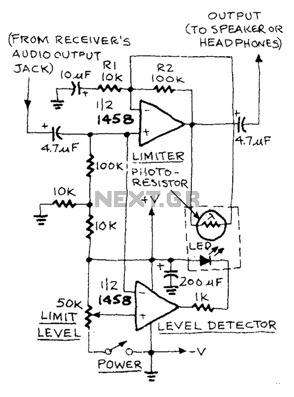
The AUD.LIMITER circuit features a level trim potentiometer that allows for adjustment of the limiting level. When the input signal exceeds the set level of the potentiometer, the output from one half of the operational amplifier, functioning as a...
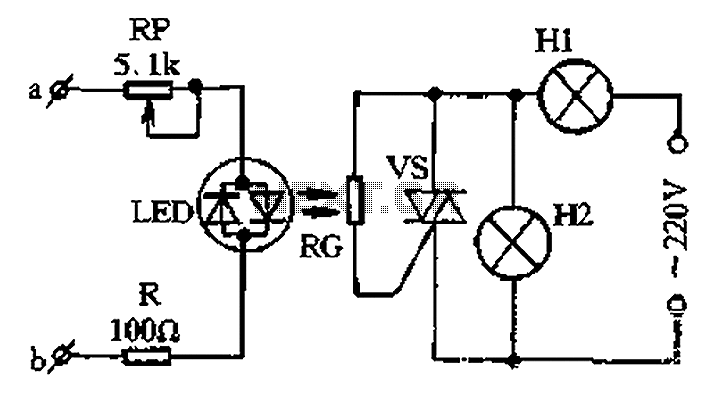
The circuit for a two-color music lantern controller is illustrated in Figure 1-44 below. Terminals a and b are located at both ends of the speaker, which receives audio signals. The audio signal is processed through a sensitivity adjustment...
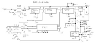
This 860 MHz Phase Locked Loop (PLL) oscillator circuit is designed for a 1200 MHz transverter's local oscillator with 435 MHz rigs. The oscillator utilizes Toshiba PLL synthesizer integrated circuits (ICs). The TC9122P serves as a preset counter for...
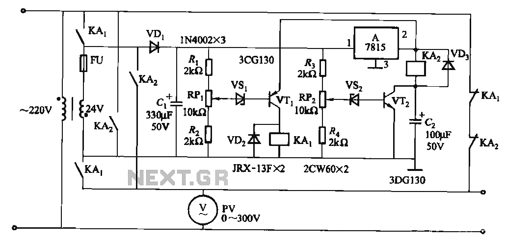
When the input voltage is in the range of 170-260V AC, the output AC voltage falls between 187-231V. The transformer ratio is k = 24/220 = 0.11. If the input voltage drops below 170V, relay KAi activates (adjusted by...
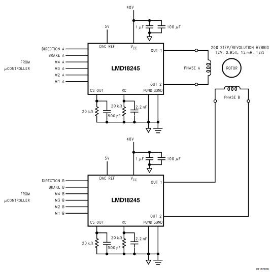
LMD18245 bipolar stepper motor driver circuit design using few electronic parts The LMD18245 is a versatile bipolar stepper motor driver designed to control stepper motors with precision and efficiency. This circuit utilizes a minimal number of electronic components, making it...
The working principle of this inexpensive and simple-to-build metal detector circuit involves mixing two equal frequencies, which results in a low-frequency interference. The metal detector circuit operates on the principle of heterodyning, where two frequencies are combined to produce a...
Warning: include(partials/cookie-banner.php): Failed to open stream: Permission denied in /var/www/html/nextgr/view-circuit.php on line 713
Warning: include(): Failed opening 'partials/cookie-banner.php' for inclusion (include_path='.:/usr/share/php') in /var/www/html/nextgr/view-circuit.php on line 713