
Driving a servo with MOSFET
To construct a battery-powered device with a servo motor and effective power management, a comprehensive understanding of MOSFET operation and circuit design is essential. The circuit should include a battery source, a servo motor, and a MOSFET that will act as a switch to control the servo's power supply.
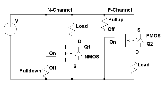
The circuit design can start with an N-channel MOSFET for low-side switching. This configuration typically provides better efficiency and thermal performance. The MOSFET should be rated for a voltage higher than the battery voltage and for a current that exceeds the servo's stall current. A common choice for such applications is the IRF520 or similar devices.
To control the MOSFET, a microcontroller or a simple switch can be used. If a microcontroller is employed, a GPIO pin can be connected to the gate of the MOSFET through a resistor (typically 10kΩ) to limit the current. A pull-down resistor (around 10kΩ) should also be connected from the gate to ground to ensure that the MOSFET remains off when not driven by the microcontroller.
For the servo motor, the power supply should be connected to the drain of the MOSFET, while the source is connected to ground. The servo's control signal can be connected directly to the microcontroller's PWM output pin, allowing for precise control over the servo's position.
In the case of using a P-channel MOSFET for high-side switching, the circuit configuration will differ slightly. The source of the P-channel MOSFET should be connected to the positive voltage supply, while the drain connects to the servo motor. The gate of the P-channel MOSFET should be driven low to turn on the device, which can be achieved through a microcontroller output, with a pull-up resistor connected to the positive supply.
In either case, it is crucial to ensure that the MOSFET is adequately rated for the application and that appropriate heat dissipation measures are in place, such as using a heatsink if necessary. Additionally, including bypass capacitors near the power supply pins of the servo can help stabilize the voltage and improve performance.
This design approach provides a robust solution for controlling a servo motor in a battery-powered application while conserving battery life through effective switching techniques.Build a small battery powered device containing a servo. I would like to be able to turn off the servo to save battery life. I have read previously that MOSFETs can be used to do this, but I am having trouble finding example circuits that are detailed enough (missing resistor values with no way to calculate them) and to be honest Iam not too sure what sort of circuit I am looking for (I have never used any FETs before). Can someone please give me a nudge in the right direction If you want practical guidance, including part selection, look at some of the speed control projects for R/C systems which have been published - preferably a recent one. A FET that can run the drive motor should have little trouble with a servo. One thing to think about is if you could get away with using an N-channel device to switch the low side as those are fundamentally better than the P-channel devices.
However, the brushless motor controllers that are all over the place today use both, so you could pick a P-channel device and drive circuit from there for high side switching. Chris Stratton Aug 1 `12 at 14:56 🔗 External reference
Related Circuits
Create an H-Bridge for controlling a DC brushed motor using PWM. One bridge will control one DC motor. The bridge will have three inputs: A, B, and PWM. Inputs A and B will determine the direction of the motor,...

The Servo Timer II was primarily designed for parachute deployment on water rockets but can be used for other applications. The timer controls a single RC servo motor that can open a latch on a parachute door. Once triggered,...
Sun tracking systems significantly enhance the efficiency of photovoltaic (PV) arrays and are crucial for concentrated PV systems. This document discusses a light tracking servo model designed to simulate the movement of a PV array. A mathematical model is...

The plan for the full bridge inverter circuit involves using IRF2807 MOSFETs (75V Vds, 82A Ids) and two IR2110 driver ICs. Previous attempts to create an H-Bridge for a DC motor were unsuccessful. The DC input voltage is 34V,...
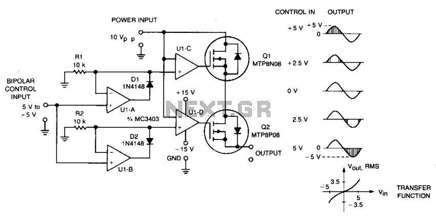
This circuit accepts bipolar control inputs of ± 5 V and provides a phase-chopped output to a DC load (such as a servo motor) of the same polarity as the input. The RMS voltage of the output is closely...
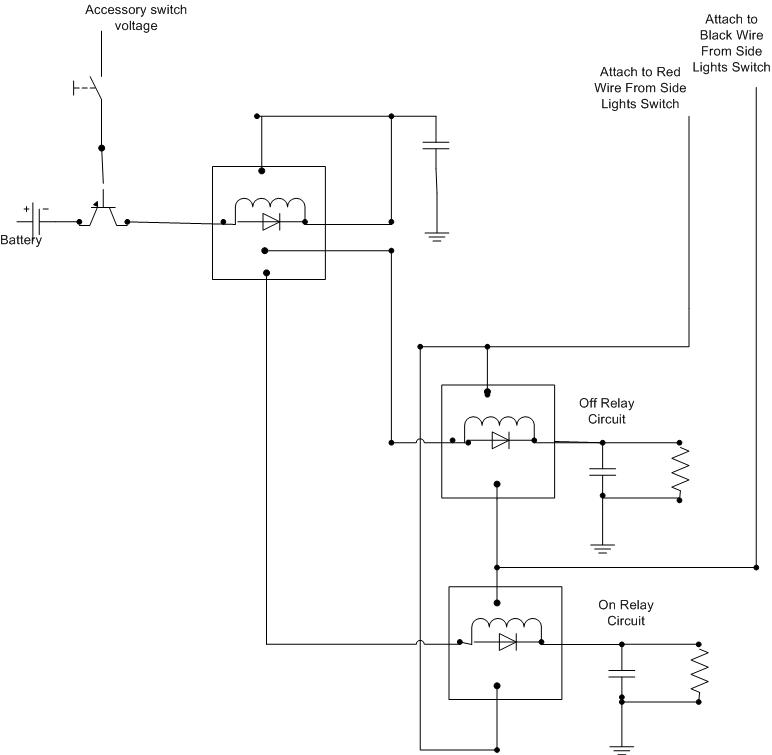
A decision has been made to install daytime driving lights for an Elise vehicle. The intention is to eliminate the need for manually pressing the button on and off repeatedly. The installation of daytime driving lights (DRLs) enhances vehicle visibility...