
AT89C2051 Night Light Saver
The Saver V5.0 circuit is designed for efficient control of a night light based on a simple time schedule. It employs the AT89C2051 microcontroller, which serves as the core processing unit. The microcontroller's clock signal is generated by a Schmitt trigger inverter (CD4093), which ensures a stable and reliable oscillation at approximately 680 kHz, suitable for the timing functions required in this application.
The system's timekeeping is synchronized with the 50 Hz mains frequency, providing a reference that enhances accuracy. Users can set the operational time for the night light by pressing a designated button at 18:00. This simple user interface allows for straightforward programming of the light's on and off cycle, ensuring that the light is operational during the evening hours.
In the event of a mains power failure, the system incorporates a visual indicator in the form of a blinking LED. This feature alerts users to the power interruption, prompting them to reset the system by pressing the time set button again. The absence of battery backup means that the system relies entirely on the mains power for operation, which simplifies the design and reduces costs but requires user intervention in case of a power outage.
The output stage of the circuit is designed to drive a 25W incandescent lamp, which is a common choice for night lighting applications. The circuit's design ensures that it can handle the necessary load without overheating or experiencing performance issues. Overall, the Saver V5.0 represents a practical solution for automated night lighting, combining low cost and ease of use with essential functionality.The Saver V5. 0 runs simple clock emulation program, turns a night light on and off with preset time, say 19:00 to 22:00 everyday. The design features low cost, easy installation, no battery backup and no EMI. The AT89C2051 uses external oscillator generated by Schmitt trigger gate CD4093, ~680kHz. Reference frequency was derived from 50Hz main lin e. Time setting only allows at 18:00 by pressing time set button once. If main line has failed, functioning LED will blink at high rate. Since there is no battery backup, thus repressing the button is then needed. The output is capable of driving say, a 25W incandescent lamp. 🔗 External reference
Related Circuits
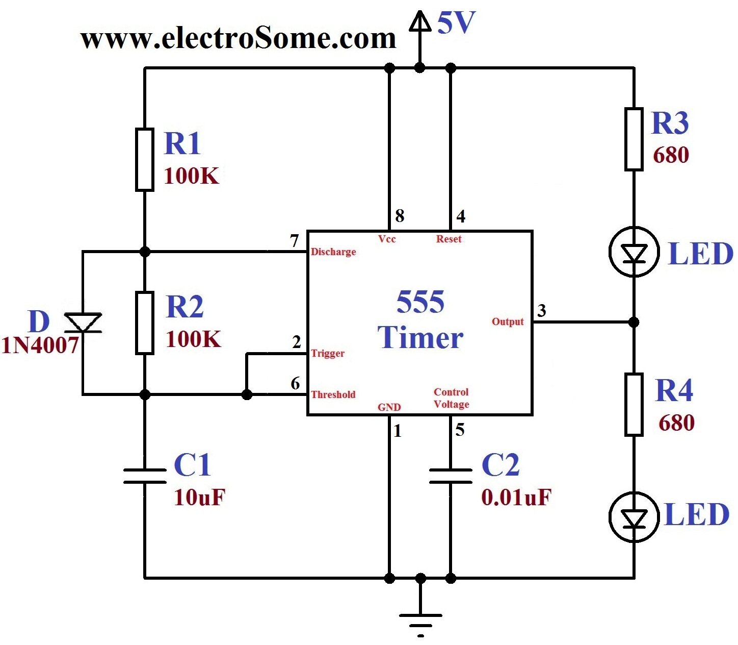
A dancing light can be easily constructed using a 555 timer wired in astable mode. This circuit alternately blinks two LEDs with a certain delay and can be modified to include additional LEDs or to control incandescent lamps. The...
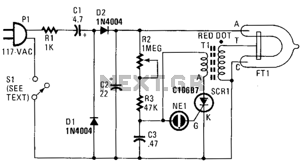
In this strobe light, two circuits are required: one circuit charges a capacitor to create a 320 V DC potential between the cathode and anode of the flashtube, while the other circuit generates bursts of approximately 4000 V to...
This is a light dimmer circuit. It does not include any special features and is a typical TRIAC-based dimmer circuit. This circuit is designed to operate with... A TRIAC-based light dimmer circuit is a common electronic design used to control...
A modified piezoelectric ceramic acoustic-electric transducer is utilized to create a sound and light control system for a stairway walkway with a delay lighting switch. The circuit structure is relatively simple, consisting of diodes VD1 to VD4 and a...
This circuit controls five outputs at 220V. A potentiometer adjusts the speed, and a switch selects the effect (one direction or both directions). The circuit includes a divider by 10 (4017), a transistor oscillator (2N2646), the power stage, and...
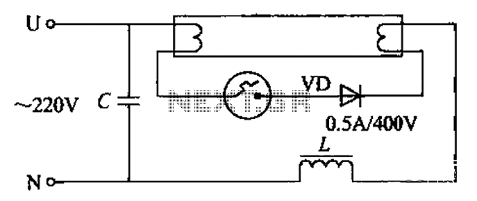
By incorporating a second pull tube into the circuit during the starter ionization phase, the positive half-cycle diode conduction results in an approximate DC current flow. This current is rectified, and due to the small ballast impedance, the instantaneous...