
Light Sequencer 5 Channels 220V

This circuit is designed to manage five 220V outputs, providing versatility through speed control and directional selection. The core of the circuit utilizes a CD4017 decade counter, which is configured to count pulses received on pin 14. The outputs are activated in a specific sequence, allowing for a range of applications such as lighting control or motor speed regulation.
The inclusion of a potentiometer allows for fine-tuning of the pulse rate, which directly influences the operational speed of the outputs. The switch enables the user to select between one-directional or bi-directional operation, enhancing the circuit's functionality.
The transistor oscillator, utilizing the 2N2646 transistor, generates the necessary timing pulses for the CD4017. The oscillator's frequency can be adjusted by modifying the components in the timing circuit, allowing for further customization of the output behavior.
To ensure reliable operation, 1N4148 diodes are employed to prevent backfeeding voltage into the IC, safeguarding against potential damage. The use of capacitors at the base of the BC548 transistors helps to smooth out the switching action, providing a more gradual transition between on and off states. The recommended value of 47 µF is a starting point; however, experimentation with larger capacitance values may yield improved performance in certain applications by prolonging the on-time of the outputs.
Overall, this circuit represents a practical solution for controlling multiple high-voltage outputs with adjustable speed and directional capabilities, suitable for various electronic and automation projects.This circuit controls five outputs 220V. Potentiometer change speed and a switch select effect (one direction or both directions). The circuit has a divider by 10 (4017), a transistor oscillator (2N2646), the power stage and power supply. Each pulse on pin 14 of 4017 advance to the next (the order is: 3, 2, 4, 7, 10, 1, 5, 6, 9, 11 - In that orde
r - and then repeat). If the integrated pulse is applied in pin15 back and resumes on pin 3. 4148 diodes prevent the return of power to the IC. Capacitors at the bases of transistors BC548 (47 µF) (but this value can be changed and should be tested) when higher the value output will remain switched on and off to turn off more smoothly. 🔗 External reference
Related Circuits
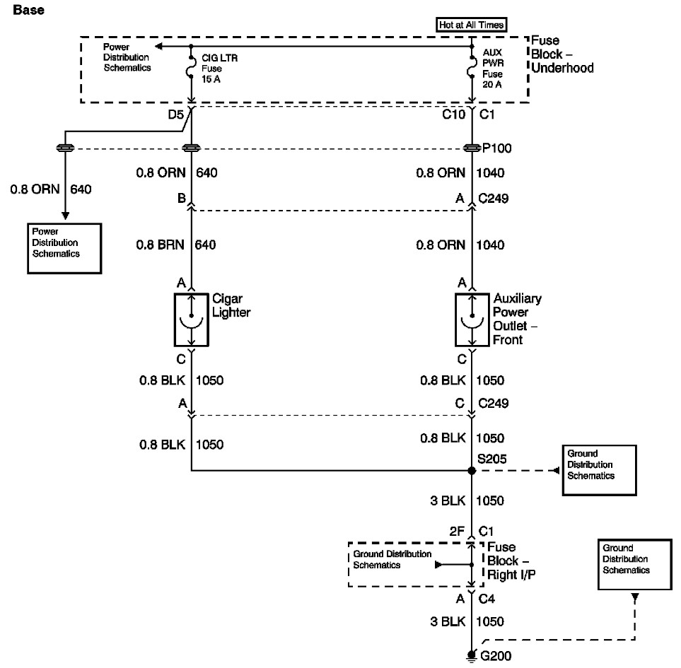
The provided information includes a fuse block diagram with the Auxiliary Power (Aux Pwr) fuse highlighted. It is advisable to check both sides of the fuse using a test light or multimeter to ensure functionality. It is assumed that...
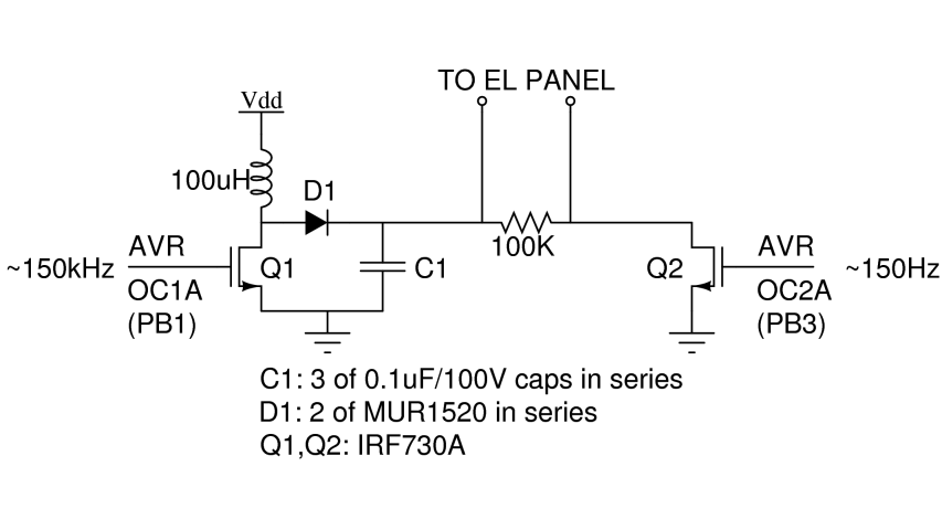
There are two primary types of backlights for LCDs: LEDs, which stands for light-emitting diodes, and EL, which stands for electroluminescent. EL backlights are generally more efficient and provide more uniform lighting compared to LED backlights, but they require...
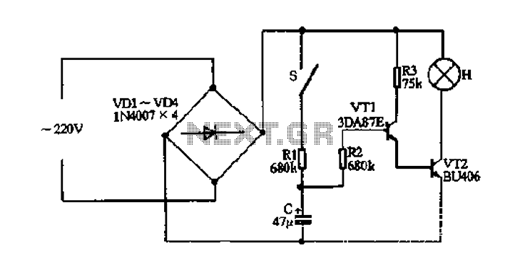
The fade circuit controls the lighting switch depicted in Figure 1-12. The figure illustrates the light switch S, H, which is responsible for lighting. Transistors VT1 and VT2, along with RC components, comprise the fade dimming control circuit. Given...
The circuit below turns on a light corresponding to the first of several buttons pressed in a "Who's First" game. Three stages are shown but the circuit can be extended to include any number of buttons and lamps. Three...
The circuit is a battery charging system powered by Q2, Q6, R8, and D10, which provides constant current to charge the battery. When an external power supply is present, the charging current flows through R8 and D10 to charge...
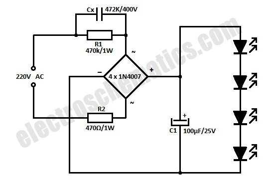
This is a simplified version of a white LED lamp that can be powered directly from the mains. It provides sufficient illumination for reading purposes. Capacitor Cx along... The circuit for the white LED lamp consists of several key components...