
ATMEGA16 8-bit AVR Microcontroller with 16K Bytes In-System Programmable Flash
The AVR programmer described is designed for efficient programming of various ATMEL AVR microcontrollers, specifically targeting models such as ATmega103, ATmega161, and ATmega163. The construction of this programmer can be accomplished quickly, making it accessible for hobbyists and engineers alike. The reliability of this programmer surpasses that of many commercially available options, which is a significant advantage for users requiring consistent performance in their projects.
The FLY3000 wireless development board expands the functionality of the AVR programmer, allowing for the integration of wireless communication modules. The compatibility with various RF modules, including NRF2401, nRF24L01, RF903, CC1020, NRF905, CC1100, and Si4432, facilitates the development of a wide range of wireless applications. This versatility makes the FLY3000 an ideal choice for projects that require wireless data transmission or remote control capabilities.
In addition to the programmer and development board, the article outlines the construction of a frequency meter, which is capable of measuring frequencies up to 40 MHz with a high degree of accuracy. This feature is particularly useful for debugging and testing circuits, as it enables users to ascertain the operational frequencies of their designs with minimal error.
The line follower robot project detailed in the document showcases practical applications of the ATmega16 microcontroller. The robot is comprised of three key modules: the sensor module, which detects the line; the microcontroller module, which processes the sensor data; and the DC motor module, which drives the robot's movement. The inclusion of an IR sensor schematic and a mainboard schematic that integrates the microcontroller with a DC motor driver provides a comprehensive understanding of the circuit design, allowing for effective implementation and troubleshooting of the robot's functionalities.This simple AVR Programmer able to transfer hex programs to mostATMEL AVR microcontrollers. It is more reliable than most other simpleAVR programmers available out there and can be built in very shortamount of time. This Programmer support the AVR microcontroller ATmega103, ATmega161, ATmega163, ATmeg.- Master MCU based on the AVR multi
function wireless development board- FLY3000, FLY-3000, wireless development board using AVR the series of Atmega16L, apply to the wireless module of the application development NRF2401 nRF24L01 RF903 The CC1020 NRF905 the CC1100 Si4432 and o. This simple AVR Programmer able to transfer hex programs to most ATMEL AVR microcontrollers. It is more reliable than most other simple AVR programmers available out there and can be built in very short amount of time.
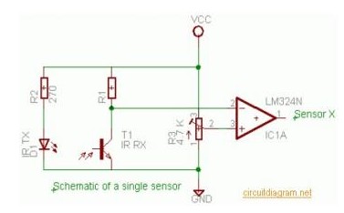
This Programmer support the AVR microcontroller ATmega103, ATmega161, ATmega163, . This article shows how to build a small, cheap and simple frequency meter, without any fancy, out of reach components. The simple proposed design can measure frequencies up to 40 Mhz with errors below 1%! This degree of precision will be more than enough to debug most of your analog and digital circ. Here the complete electrical circuit diagram of line follower robot which built based on ATmega16. There are three modules of line follower robot circuit that are sensor module, microcontroller module and DC motor module.
IR sensor schematic diagram:Mainboard (microcontroller + DC motor driver schema. Here the complete electrical circuit diagram of line follower robot which built based on ATmega16. There are three modules of line follower robot circuit that are sensor module, microcontroller module and DC motor module. IR sensor schematic diagram:Mainboard (microcontroller DC motor driver schemati. 🔗 External reference
Related Circuits

When the preset is set to its maximum, the LED flashes at a rate of approximately once every half second. This rate can be increased by raising the capacitor value from 10µF to a higher value. For instance, if...
is circuit was requested from an email. It will allow your car headlights to flash on and off at the same time or it will cause them to flash alternately. The circuit is based on the 555 timer. It...
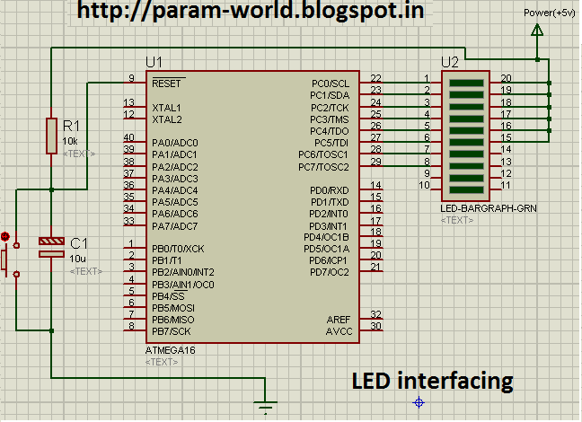
The circuit interfaces an LED with an AVR microcontroller (ATMega16). The components used include one ATMega16 microcontroller, a 10K resistor, a 16uF/25V capacitor, a push button switch, and a green LED bar instead of eight individual LEDs. The power...
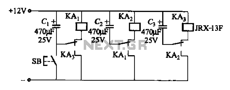
The relay control allows for multiple pairs of contacts to be connected in parallel, enabling the circuit to handle a large lamp power. The design is straightforward; by simply changing the capacitance of the capacitor, different flash frequencies can...
This simple flashing light circuit operates at 6 volts and 0.5A, exhibiting low current consumption when the light bulb is turned off. The frequency of the flashing is predetermined. The circuit consists of a power supply, typically a battery or...
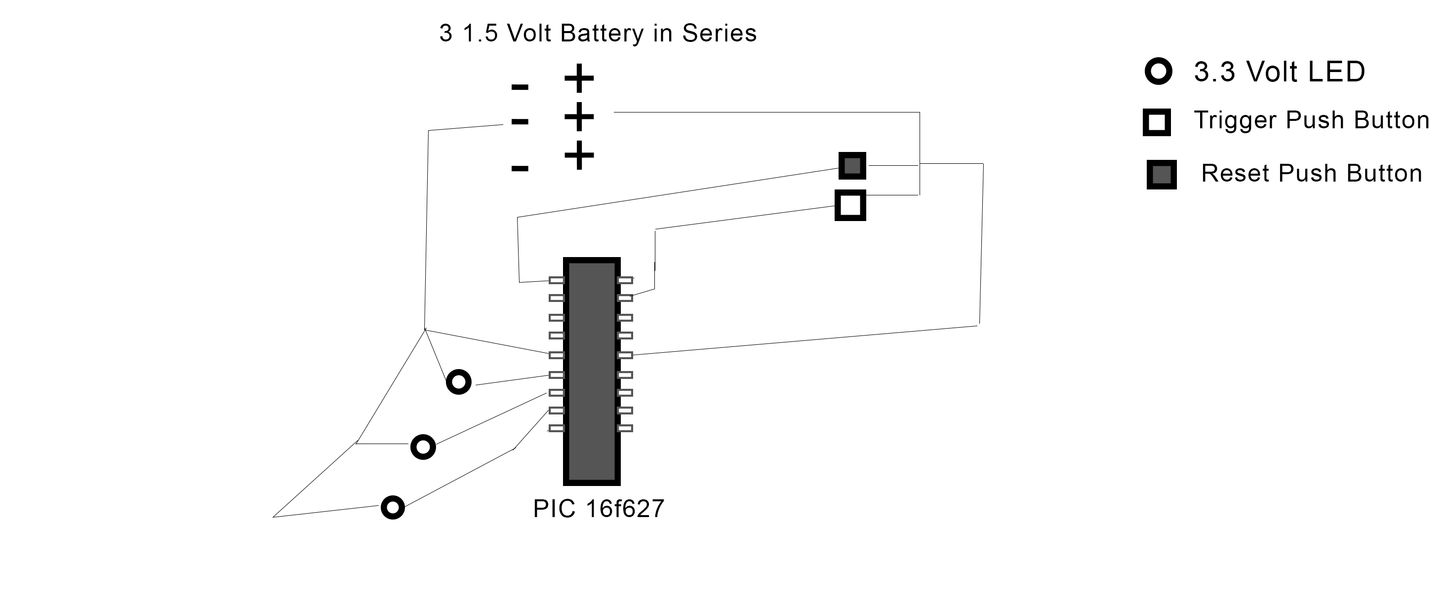
The PIC 16F627 microcontroller has been programmed to activate three LEDs when a trigger pushbutton is pressed. Additionally, when a reset pushbutton is pressed, a shutdown sequence is initiated where each LED turns off sequentially with a 5-second delay...
Warning: include(partials/cookie-banner.php): Failed to open stream: Permission denied in /var/www/html/nextgr/view-circuit.php on line 713
Warning: include(): Failed opening 'partials/cookie-banner.php' for inclusion (include_path='.:/usr/share/php') in /var/www/html/nextgr/view-circuit.php on line 713