
atmega32 circuit

No description available.
Related Circuits
The circuit designed for distortion measurements eliminates the fundamental frequency of 1 kHz, enabling the assessment of the residual harmonic levels. Initially, a true RMS meter is employed to measure the 1-kHz input level (E^) by positioning the switch...
Using high-beam headlights while driving on the highway can significantly enhance visibility; however, they may pose a blinding risk to other drivers. This straightforward circuit can be integrated into the headlight switch to enable automatic switching between high and...
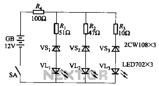
When the supply voltage falls below 10.2V, the yellow light-emitting diode (LED) VLi illuminates, indicating that the storage pool can no longer continue to discharge. Additionally, when the voltage exceeds 16.2V, the yellow, green, and red light-emitting diodes (LEDs)...
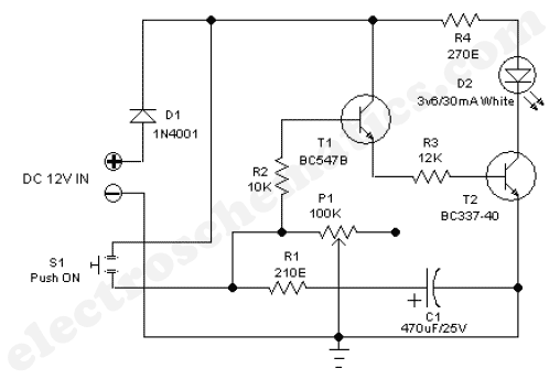
The 555 adjustable timer circuit initiates timing upon activation. A green LED illuminates to indicate that the timing process is underway. Once the designated time period concludes, the... The 555 timer IC is a versatile device widely used in various...
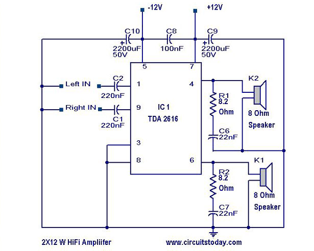
A simple Hi-Fi amplifier circuit diagram with a schematic for creating an audio amplifier, designed using the TDA 2616 integrated circuit (IC), which is a stereo power amplifier. It is suitable for use with radios, tape players, and televisions,...
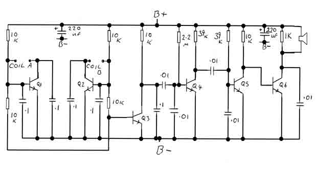
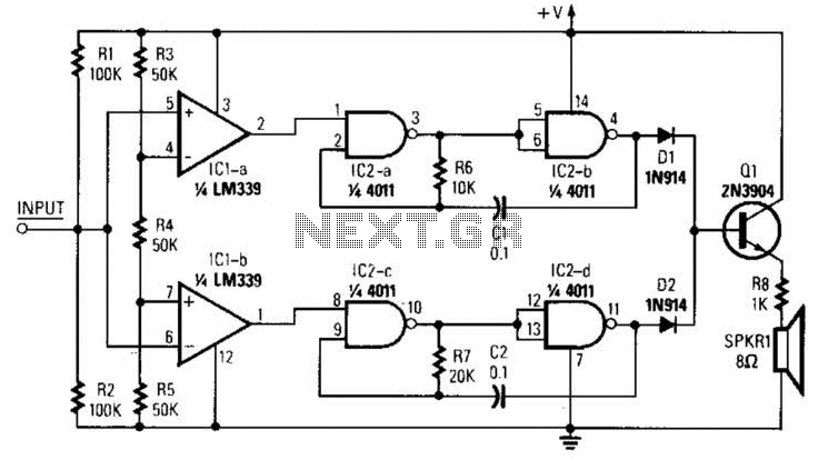
By adjusting the oscillators so their frequencies are very nearly the same, the difference between them is made audible as a beat note. This beat note changes slightly when the search loop is moved over or near to a...