
BFO metal Detector Circuit
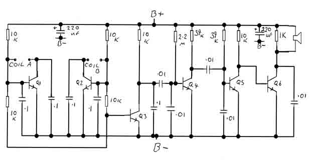
Parts list
Power source: Any 9V battery PP3 is ideal.
Capacitors: 2 off 220 µF 16V electrolytic. 5 off 0.01 µF polyester. 5 off 0.1 µF polyester.
Resistors: All resistors 1/4 watt 5% 6 off 10 k 1 off 1 k 1 off 2.2 m (2.2 Mega ohm) 2 off 39 k
Transistors: All BC 184B, or 2N3904, or 2N2222A. Just about any small signal NPN with a gain of 250+ will do. There are hundreds to choose from.
Audio output: A 2.5 inch 8 ohm speaker will work but headphones or earpiece are preferable; the higher the impedance, the better.
Many of the above parts could be salvaged from a broken transistor radio or purchased from companies like RS Components, Maplin Electronics, Radio Shack, or Digikey whose ads often appear at the top of this page.
Once the components have been obtained, the circuit can be built in a few hours using copper clad stripboard, or if the facilities are available, a printed circuit board can be made using the layout below. The original layout should print out at about 50 mm x 100 mm.
Coils: This is the only tricky part. The search loop is best wound onto a plywood former. Method 1: Cut three circles from some 3 mm plywood, one 15 cm diameter and two 16 cm diameter. Using wood glue, make a sandwich with the 15 cm circle in the center. When the glue has set, wind 10 turns of 0.25 mm enameled copper wire around the groove in the edge of the former. Connect this coil when finished to the points marked coil 1 on the schematic. Method 2: Cut a 16 mm diameter circle from some 10 mm plywood. Then, with this circle clamped in a vice, run a saw around the edge of the circle to make a slot about 5 mm deep and 2 mm wide around the edge to accommodate the windings. If an oscilloscope or frequency counter is available, make a note of the frequency. Ideally, this coil will be oscillating at about 104 kHz, with an amplitude of about 0.5 V peak to peak. The second or reference oscillator needs to be made much smaller and, if possible, attached to the control box so it can be adjusted as the detector is used. To make a really good adjustable reference oscillator, visit a DIY store for some plastic water fittings. The smaller one is the inlet pipe to a plastic ball valve assembly fitted with a brass nut. The larger one is a plastic tank connector fitted with a brass nut from an old tap. Both of these work well and should be glued to the control box in a position where they can be adjusted. The reference coil itself is wound on a piece of wood or plastic about 10/12 mm in diameter and about 50 mm long. The actual number of turns of this coil depends on the diameter of the former and can only be found by experiment. Start with about 125 turns of 0.25 mm enameled copper wire (this coil, when finished, has to fit inside the plastic tube) and remove turns until the two frequencies are close. This coil is attached to the circuit board at points marked coil 2. If all is well, the detector should be howling at this point. When the two oscillators are well matched, it should be possible by adjusting the brass nut in or out to bring the beat note to a halt or null.By adjusting the oscillators so their frequencies are very nearly the same, the difference between them is made audible as a beat note, this beat note changes slightly when the search loop is moved over or near to a piece of metal. It has been found in practice best to make the search oscillator fixed say at 100khz and to arrange for the reference oscillator to be adjustable 100khz plus or minus 250hz.
This gives a beat note of 250hz to 0 to 250hz. The beat note disappears or nulls when the two oscillators are about equal. This type of detector is most sensitive when the beat note is close to zero, about 5hz ( motor boating ) any slight change being noticeable. Parts list Power source: Any 9v battery PP3 is ideal. Capacitors: 2 off 220uF 16v electrolytic. 5 off .01uF polyester. 5 off .1uF polyester. Resistors: All resistors 1/4 watt 5% 6 off 10k 1 off 1K 1 off 2.2m ===== 2.2 Mega ohm 2 off 39k Transistors: All BC 184B, or 2N3904, or 2N2222A. Just about any small signal npn with a gain of 250+ will do. There are hundreds to choose from. Audio output: A 2.5 inch 8 ohm speaker will work but headphones or earpiece are preferable the higher the impedance the better.
Many of the above parts could be salvaged from a broken transistor radio, or purchased from companies like RS Components, Maplin Electronics, Radio Shack, or Digikey who's adds often appear at the top of this page.. Once the components have been obtained the circuit can be built in a few hours using copper clad stripboard, or if you the facilities make a printed circuit board using the layout below.
The original layout as below should print out at about 50mm x 100mm. Coils This is the only tricky part. The search loop is best wound on to a plywood former. Method 1: Cut three circles from some 3mm plywood, one 15cm diameter and two 16cm diameter. Using wood glue make a sandwich with the 15cm circle in the center. When the glue has set you can wind 10 turns of . 25 mm enameled copper wire around the groove in the edge of the former. Connect this coil when finished to the points marked coil 1 on the schematic. Method 2: Cut a 16mm diameter circle from some 10mm plywood. Then with this circle clamped in a vice run a saw around the edge of the circle so as to make a slot about 5mm deep and 2mm wide around the edge to accommodate the windings. If you have access to an oscilloscope or frequency counter make a note of the frequency. Ideally This coil will be oscillating at about 104khz, with an amplitude of about .5v p to p. The second or reference oscillator needs to be made much smaller and if possible attached to the control box so it can be adjusted as the detector is used.
To make a really good adjustable reference oscillator you will have to visit a DIY store, what you need are some plastic water fittings, two examples are shown below. The smaller one is the inlet pipe to a plastic ball valve assembly fitted with a brass nut. The larger one is a plastic tank connector fitted with a brass nut from an old tap. Both of these work well and are glued to the control box in a position where they can be adjusted. The reference coil itself is wound on a piece of wood or plastic about 10/12mm diameter and about 50mm long The actual number of turns of this coil depends on the diameter of the former and can only be found by experiment.
Start with about 125 turns . 25 enameled copper wire ( this coil when finished has to fit inside the plastic tube ) and remove turns until the two frequencies are close. This coil is attached to the circuit board at points marked coil 2. If all is well the detector should be howling at this point. When the two oscillators are well matched it should be possible by adjusting the brass nut in or out to bring the beat note to a halt or null.
🔗 External reference
Related Circuits
This is a 10 GHz frequency amateur radio waveguide detector. The 10 GHz amateur radio waveguide detector is designed to operate within the microwave frequency range, specifically targeting the 10 GHz band commonly used in various amateur radio applications. The...
This circuit was designed to transmit commands over an LNB coaxial cable. An LNB (Low-Noise Block downconverter) is commonly used for satellite TV reception and is positioned at the focal point of a satellite dish. The circuit generates a...
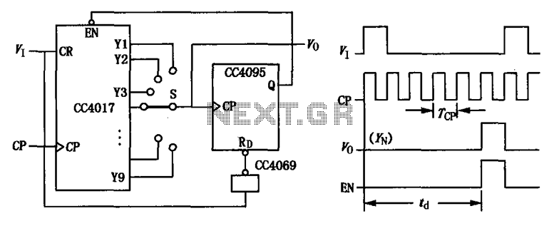
CC4017 counter/distributor featuring a circuit diagram of the delay. The CC4017 is a decade counter and distributor that counts from 0 to 10, providing ten output states. It is commonly used in various digital applications for counting purposes, such as...
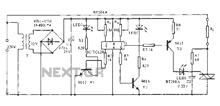
The built-in temperature sensor is utilized to control the triac TC620 for temperature regulation. The adjustment circuit, consisting of resistors Rp1 and Rn, allows for modifications to the lower temperature limit. When the ambient temperature exceeds this lower limit,...
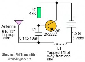
This is likely the simplest radio transmitter available, consisting of five components and capable of being assembled in a compact space. It is suitable for science fair projects or other science-related endeavors where short-range transmission is beneficial. The device...
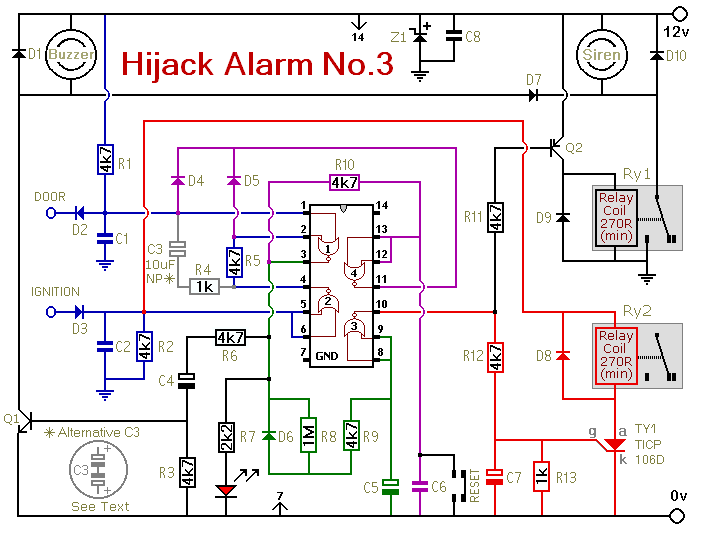
Similar to the initial two Hijack Alarms, this circuit is designed to activate if a door is opened while the ignition is switched on. After a delay of several minutes, allowing the thief to move a safe distance away,...
Warning: include(partials/cookie-banner.php): Failed to open stream: Permission denied in /var/www/html/nextgr/view-circuit.php on line 713
Warning: include(): Failed opening 'partials/cookie-banner.php' for inclusion (include_path='.:/usr/share/php') in /var/www/html/nextgr/view-circuit.php on line 713