
Audible Flasher Warning

The circuit operates by utilizing a 555 timer IC configured in astable mode, generating a square wave signal that is responsible for controlling the piezo sounder. The piezo sounder emits an audible beep to remind the rider to cancel the indicators. The circuit is designed to be robust and reliable, making it suitable for outdoor use on motorcycles and scooters.
The power supply for the circuit is derived from the vehicle's flasher relay, ensuring that the circuit is only active when the indicators are engaged. This design minimizes unnecessary power consumption and enhances the longevity of the components. The bridge rectifier (D1-D4) converts the AC signal from the relay into a DC voltage, which is then smoothed by capacitor C1. Diode D5 serves a critical role in maintaining a steady voltage supply to the 555 timer by preventing back discharge from the capacitor during the off periods of the flasher.
The timing components, including resistors R1, R2, and potentiometer P1, along with capacitor C2, determine the timing intervals for the sounder activation. The use of a potentiometer allows for fine-tuning of the delay according to user preference, accommodating different riding styles or preferences for audible reminders.
The circuit's enclosure is designed to be splash-proof, protecting the electronic components from moisture and debris commonly encountered in outdoor environments. This design consideration is crucial for ensuring the reliability and durability of the circuit over time. The flexibility in the placement of the sounder allows for optimal sound projection while maintaining the integrity of the control unit's housing.
Overall, this circuit enhances rider safety by providing an effective reminder system for indicator cancellation, allowing riders to maintain their focus on the road. The simplicity of the design, coupled with the ease of installation, makes it an attractive addition for any biker or scooter rider seeking to improve their riding experience.If you`re a biker or scooter rider you`ll know how easy it is to forget to cancel your flashing indicators after turning without an audible reminder. Constantly glancing at indicator lamps is hardly an option; your eyes should be on the road ahead! The simple circuit shown here provides an audible reminder. The clever bit is the way it doesn`t ann oy you by beeping the instant you activate the flashers but only after a preset time, in other words when your indicators are active longer than normal. Supply to the circuit is through the flasher relay. With the indicators activated a squarewave voltage reaches bridge rectifier D1-D4 via terminal T1 or T2, with the other terminal remaining grounded through the indicator lamp that`s inactive.
The pulsed DC voltage is stored and smoothed in C1, with D5 preventing the electrolytic from discharging during the periods when the flasher voltage is off. This also provides an adequately clean supply voltage for the 555 timer whenever the indicators are operating.
Timer IC1 is used here as an oscillator and controls a piezo sounder by means of transistor T1. The output of the 555 is active Low, meaning that initially the transistor is blocked and the sounder is silent. The timer always charges and discharges capacitor C2 to a level between a third and two-thirds of the operating voltage, producing an interval of 0.
7 x C2 x (R2 + R1 + P1) [s] The preset enables you to set this delay up to a second or so. The initial delay, before the sounder first operates, is significantly longer, however, because the electrolytic has zero charge. Only after this delay is the output active, for the pulse duration of 0. 7 x C2 x R2 (equivalent to about 0. 15 seconds), enabling the sounder to operate. This applies only when +12 V is present at the collector of transistor T1, which is the situation when the flasher relay is just switched on and the indicator bulbs light up.
The circuit is built inside a splash-proof enclosure, installed on your machine in a position that`s out of harm`s way. The audible sounder can be positioned anywhere outside the enclosure if it`s a waterproof type. The audible control unit requires only two cable connections, which can be made at any convenient access point.
🔗 External reference
Related Circuits

The LED flasher circuits operate on a single 1.5-volt battery. The circuit on the upper right utilizes the widely used LM3909 LED flasher integrated circuit (IC) and requires only a timing capacitor and an LED. The LM3909 is a specialized...

This simple circuit utilizes NAND gates to alternately flash two LEDs. The two 47µF capacitors set the flashing frequency. It is advisable to include a decoupling capacitor across the power supply. The circuit was constructed using the specified components...
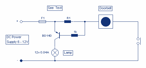
This circuit will light a lamp at a remote location when the doorbell switch is pressed. This circuit should only be used with the solenoid type doorbells; the electronic type that play tunes will not work here. It is...
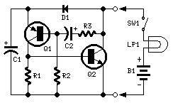
Ideal to operate 3 to 24V DC existing on-circuit lamps. LED operation is also possible. This circuit was designed to provide that continuous light lamps already wired into a circuit become flashing. Simply insert the circuit between existing lamp...

The hobby circuit described can be connected to a 3V battery to provide a warning when the battery is nearing its end of life. It will flash an LED when the battery voltage drops to approximately 2.4 volts. The...
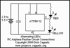
This was designed to flash a pair of LEDs to be mounted on the wing tips of a Parkzone Citabria R/C (remote control) airplane. The unmodified Parkzone Citabria only weighs 20 grams (about 0.7 oz), so weight, and therefore...