
Press light switch double circuit 3

The Darlington touch switch circuit operates on the principle of capacitive sensing, where the touch-sensitive sheet detects the presence of a finger, allowing for a non-mechanical method of switching. The isolation provided by the transformer ensures that the low-voltage side of the circuit is safe for user interaction. The use of a bridge rectifier allows for efficient conversion of AC to DC, which is essential for the operation of the Darlington transistors that act as amplifiers for the base current.
The design of the circuit includes a self-locking mechanism, which means that once activated, the relay remains engaged until a specific action is taken to deactivate it. This feature is particularly useful in applications where a stable and continuous light source is desired without the need for constant interaction. The choice of components, such as the JZC-22F relay, is crucial for ensuring reliability and performance under varying load conditions.
The touch electrode's design is also significant; it is made from readily available materials, making it cost-effective and easy to fabricate. The size and shape of the electrode influence the sensitivity of the touch detection, and the distance between the electrodes is optimized for effective operation. The entire assembly is enclosed in a plastic housing to protect the components and ensure user safety.
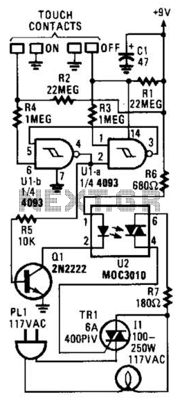
Overall, the Darlington touch switch circuit presents an innovative solution for touch-sensitive control in various applications, combining safety, reliability, and ease of use in its design.Darlington is a tube made double clam touch switch circuit is characterized by a touch sheet and 20V AC mains through the power transformer T isolated, relatively safe. After t he circuit is powered, 2pOV Optional AC transformer T Buck, VDl-VD4 bridge rectifier and C. Filtering, mountain about 10V DC voltage output for the Darlington circuit and a relay switch control circuit electricity. Darlington VT1 and VT2 are in the OFF state state, two station contact K of relay point kl and k-2 are open, lights finger pressing a r electrode sheet M2, a DC voltage by a finger iL mesh l and to VT2 Tre eight base current, VT2 conduction, the relay station K was jU slow, contact k1, k2 closed.
Sheet 1. k-2 so that F Sh electroluminescent lamp, k1 resistor R. Access circuit so that when the circuit self-locking finger from the M2, since the R, WJ then. Relay still stays energized, spider F always light. Suddenly turn off the lights when needed, just use your fingers to press down electrical Almost sheet Ml, this time Darlington quickly saturated conduction VT1, VT2 ridicule the base grant the potential to make a sword fell off relay and zero electrical K release, its contact station k J, k2 jump thirty. IU lamp E goes out. VT1 and VT2 to adopt a very high number of peer River enlarged u850 Darlington diode, as the reader can not find such a pipe to be used in multiples of two release Gerbera type silicon NI 200 in 0014, N diode-connected into a composite pipe instead of Darlington s tube.
K preferably JZC-22F, 22 00 ultra-compact towel power relays, it has two changeover contacts, access point capacity 2A, line package r as voltage is OV. T Oh Saikawa 220V/9V, 5VA small power converter Lian device. The touch electrode made of iron sheet available canned cut into 2-cent coin size sheet-shaped paid, then cut from the Secretary, the distance of about 1n, tr.
Left and right, and then paste it in the plastic housing L ur.
Related Circuits
In this circuit, two 567 tone decoders are utilized. One functions as an oscillator, while the other acts as a detector. Connecting TP1 and TP2 allows U2 to receive the signal from U1, resulting in pin 8 of U2...
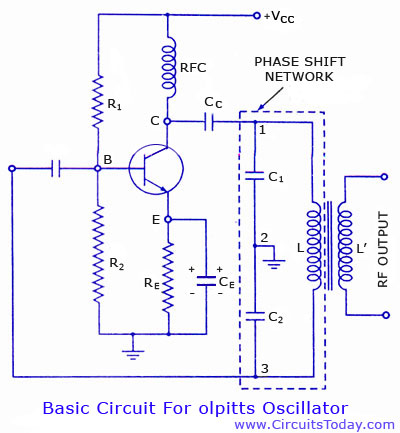
Colpitts oscillator circuit diagram and theory. Colpitts oscillator frequency equation. Colpitts oscillator using transistor. Colpitts oscillator using op-amp. The Colpitts oscillator is a type of electronic oscillator that generates sine waves and is widely used in various applications such as...
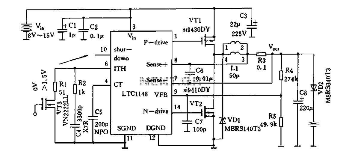
Efficient nickel-cadmium battery charger IC (LTC1148) circuit The LTC1148 is an integrated circuit designed for the efficient charging of nickel-cadmium (NiCd) batteries. This charger IC features a constant current/constant voltage (CC/CV) charging method, which is essential for optimizing the charging...
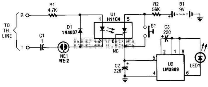
The circuit is constructed using a pair of low-cost integrated circuits (ICs): an H11C4 optoisolator/coupler with a silicon-controlled rectifier (SCR) output (U1) and an LM3909 LED flasher (U2). It connects to the phone line in the same way as...
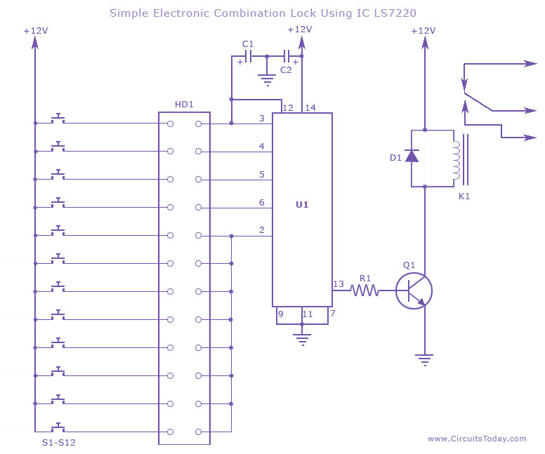
This circuit diagram illustrates a simple electronic combination lock utilizing the IC LS7220. It is designed to activate a relay for controlling any device (on & off) when a specific combination of four digits is entered. The circuit operates...

This is a 2 x 70W audio power amplifier circuit built using a single IC STA550. The amplifier circuit requires a few external components, primarily resistors and capacitors, and is straightforward to design. The STA550 audio amplifier can provide...