
Audible Logic Tester Circuit
The described circuit functions as a logic level tester, providing clear audio feedback regarding the state of digital signals. The high-impedance input allows for minimal interference with the tested circuit, ensuring accurate troubleshooting of TTL (Transistor-Transistor Logic) and CMOS (Complementary Metal-Oxide-Semiconductor) logic families.
The core of the circuit utilizes an LM339 quad comparator, which features four independent comparators. In this application, two of these comparators (IC1-a and IC1-b) are configured to establish voltage thresholds. IC1-a activates when the input voltage surpasses 67% of the supply voltage, signaling a logic high, while IC1-b activates when the input voltage falls below 33%, indicating a logic low. Resistors R1 and R2 are strategically placed to prevent false triggering of the comparators when the input is floating or within the undefined voltage range between the set thresholds.
The output from the comparators controls two gated astable multivibrators, implemented using additional sections of the LM339. The high tone generator, composed of IC2-a and IC2-b, is responsible for producing an audible high-pitched tone when a logic high is detected. Conversely, the low tone generator, utilizing IC2-c and IC2-d, emits a lower frequency tone for logic low signals.
To ensure that the outputs of the tone generators do not interfere with each other, diodes D1 and D2 are employed to isolate the signals. This isolation prevents any backflow of current that could distort the tones produced. The final output is amplified through transistor Q1, which drives a low-impedance speaker, allowing for clear and audible indications of the logic levels.
This tester is particularly useful in educational settings and practical applications where quick and reliable assessment of logic states is necessary. Its design emphasizes simplicity and effectiveness, making it an essential tool for engineers and technicians working with digital circuits. The tester provides an audible indication of the logic level of the signal presented to its input. A logic high is indicated by a high tone, a logic low is indicated by a low tone, and oscillation is indicated by an alternating tone. The input is high impedance, so it will not load down the circuit under test. It can be used to troubleshoot TTL or CMOS logic. The input section determines whether the logic level is high or low, and enables the appropriate tone generator; it consists of two sections of an LM339 quad comparator.
One of the comparators (ICl-a) goes high when the input voltage exceeds 67% of the supply voltage. The other comparator goes high when the input drops below 33% of the supply. Resistors Rl and R2 ensure that neither comparator goes high when the input is floating or between the threshold levels. The tone generators consist of two gated astable multivibrators. The generator built around IC2-a and lC2-b produces the high tone. The one built around IC2-c and IC2-d produces the low tone. Two diodes, 1 and 1)2, isolate the tone-generator outputs. Transistor Ql is used to drive a low-impedance speaker. 🔗 External reference
Related Circuits
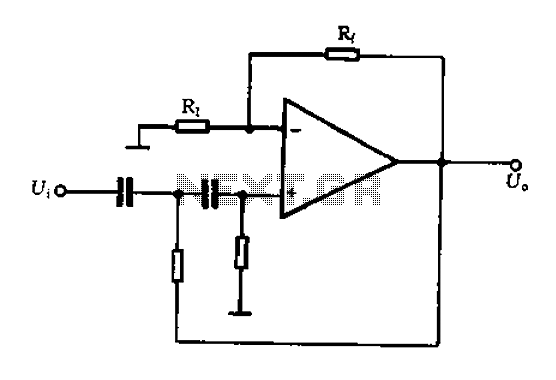
A typical two high-pass filter circuit. A high-pass filter (HPF) is an electronic circuit that allows signals with a frequency higher than a certain cutoff frequency to pass through while attenuating signals with frequencies lower than the cutoff frequency. A...
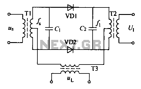
A balanced diode mixer circuit is presented, utilizing two diodes, specifically the 2AP9 model. The circuit operates with a high voltage, causing the diodes to function in an off state, which is also referred to as a diode switch...
Sometimes when experimenting with different soundcards and MIDI interfaces it is useful to see if there is some data going in MIDI interface. This can be easily tested with this adapter, which converts the midi signals to visible light...
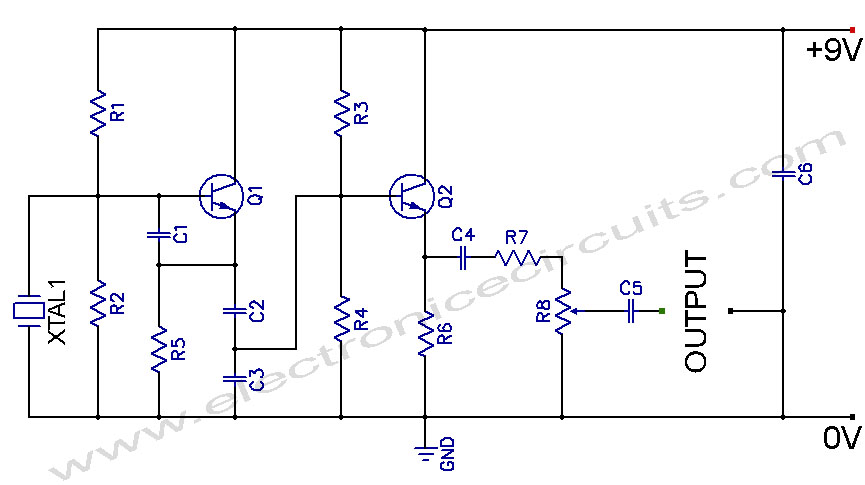
Crystal Controlled Oscillator Circuit. This general-purpose signal source is highly effective in signal-tracing applications. The output level is adjustable. The crystal-controlled oscillator circuit is designed to provide a stable and precise frequency output, which is essential for various electronic applications,...
A rain sensor alarm circuit is a useful device for alerting when rainfall occurs. The rain detector circuit presented is straightforward, utilizing only three components while maintaining high sensitivity to detect rain or moisture. The sensor can be constructed...
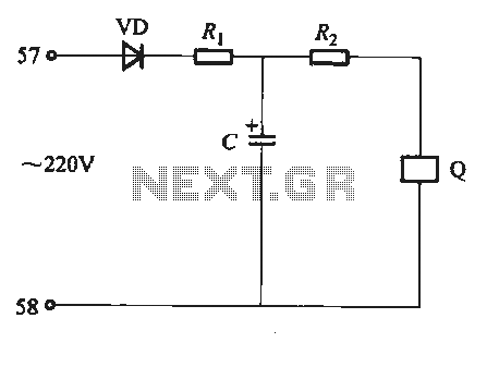
Undervoltage release operates over an extended period. When the power supply voltage drops within the operating voltage range, it triggers the release mechanism, resulting in the rotation of the tripping axle and the disconnection of the circuit breaker. There...