
Audible Transistor Tester
In this project, a comprehensive testing setup for various transistor types is established. The circuit is designed to accommodate different transistor configurations, including standard bipolar junction transistors (BJTs), Darlington pairs, and power transistors.
To initiate testing, a 9V battery is employed as the power source. It is important to note that the battery should be connected in reverse at designated points A and B. This reverse connection is a critical aspect of the testing procedure, as it allows for the evaluation of the transistors under non-standard conditions, which can reveal important characteristics such as breakdown voltages and reverse bias behavior.
The testing circuit will likely include key components such as resistors, which are used to limit current and protect the transistors during testing. A series of test points may be integrated into the schematic to facilitate easy measurement of voltages and currents at various stages of the circuit. Additionally, a multimeter can be employed to measure the collector-emitter voltage (Vce), base-emitter voltage (Vbe), and collector current (Ic) for each transistor type.
For Darlington transistors specifically, the circuit will demonstrate the high current gain characteristics, making it essential to observe the input and output relationships. Power transistors will be tested under higher load conditions to ensure they can handle the required power dissipation without failure.
Overall, the project aims to provide a thorough understanding of transistor behavior across different configurations and operating conditions, contributing to the knowledge base of electronic circuit design and analysis.All types of transistors including Darlington and power will be tested in this project. Connect the 9v battery around the other way at points A and B to test.. 🔗 External reference
Related Circuits

This simple circuit is designed to check transistors, allowing measurements down to 40 ohms across the collector-base or base-emitter junctions. It is also capable of testing output power transistors in amplifier circuits. The circuit operates with a 555 timer...
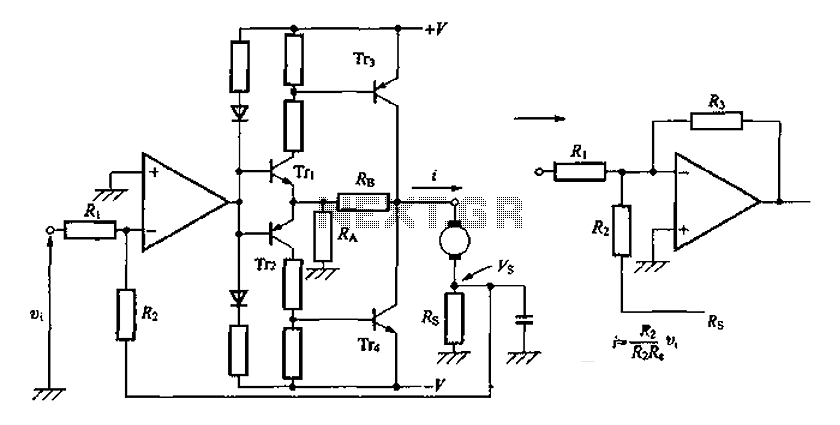
A discrete transistor current control circuit diagram. The discrete transistor current control circuit is designed to regulate the flow of current through a load by utilizing a transistor as the primary control element. This circuit typically consists of a few...

In telecommunications, Frequency Modulation (FM) transmits information over a carrier wave by varying its frequency. FM is widely utilized at VHF radio frequencies for high-fidelity broadcasts of music and speech. The global broadcast band is situated within the VHF...
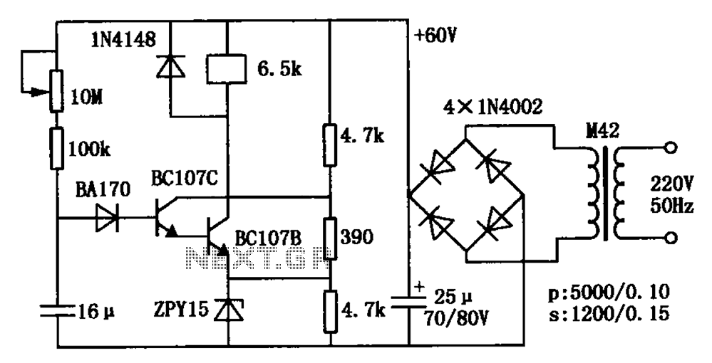
The circuit is a relay delay pull transistor configuration. Initially, when powered, the 16 µF capacitor has a voltage of zero, resulting in both transistors being off, and the relay remains inactive. As the 16 µF capacitor charges over...
This is a simple LED flasher using two 2N3904 transistors. Classic astable multivibrator using 2 transistors. Transistor is not critical. Try these: 2N4401, 2N2222, NTE123A, NTE123AP, NTE159, TUP/TUN and those in your junk box, you may find that most...
A pair of BC548 transistors has been utilized in this circuit. Although they are not specifically designed for RF applications, they still provide satisfactory performance. An ECM microphone from Maplin Electronics, model FS43W, has been employed. This is a...