
Audio 10 LED VU meter
Clearly the calibration is going to be affected by the LED operating voltages: green LEDs are higher voltage than reds and high brightness LEDs drop more voltage than low. However my experience is that any particular make/type of LED are very consistent in voltage.
This circuit was evolved quite some while ago for an audio mixing desk and it was put into production. We were at that time trying to find an IC which would do the job. Once again the circuit using mostly discrete transistors worked out easier. This was however about 15 years ago and there are newer ICs which will do the job. However when I designed this circuit these were new and quite expensive.
This is a circuit which 4QD could manufacture and sell if there were sufficient demand so if you do have a quantity application please contact us. Let me know if you have any queries or how you get on with it!
The circuit is constructed to operate with an audio power amplifier, utilizing dual power rails of +18V and -18V, with a ground reference. The design incorporates a feedback mechanism that references the LED chain to a +12V rail, necessitating a dedicated voltage stabilizer for optimal operation. A notable feature of this circuit is its series configuration of LEDs, allowing for a constant current draw of 20mA, regardless of the number of illuminated LEDs. This configuration enhances efficiency and simplifies the design compared to parallel LED arrangements.
The circuit includes two operational amplifiers (op-amps) configured as a rectifier to process the audio input signal. This rectification enables the circuit to accurately measure the audio level, which is crucial for applications like audio mixing where signal levels must be monitored. A changeover switch is integrated to toggle between average and peak reading modes, providing flexibility in signal monitoring.
The third op-amp stage implements a logarithmic scale through a five-stage feedback circuit. This stage is particularly important for visual representation of audio levels, as it allows for a more intuitive understanding of varying signal amplitudes. The feedback is dynamically adjusted based on the operating voltages of the LEDs, with diodes and resistors managing the feedback loop to the positive input of the op-amp.
Calibration of the circuit is influenced by the forward voltage drop of the LEDs used, which varies by color and brightness. Green LEDs typically exhibit a higher forward voltage than red LEDs, while high-brightness LEDs may have a greater voltage drop compared to their low-brightness counterparts. However, consistency in voltage drop is generally observed within specific LED types, allowing for reliable calibration.
Originally developed for an audio mixing desk, this circuit has proven effective and has been produced for commercial use. While there are now more modern integrated circuits available that could potentially simplify the design, the discrete transistor approach employed in this circuit was practical and cost-effective at the time of its creation. The design remains viable for production if there is sufficient demand, indicating potential for further applications in audio engineering.The circuit was designed to work with an audio power amplifier which operated off +18v-0v-18v power rails. The actual voltage used is not too critical except that the feedback is referred to the LED chain which itself is anchored to a +12v rail, hence the separate stabilizer for this.
It has one large advantage over most of the LED chips available - all the LEDs are in series so it only draws 20mA irrespective of the number of LEDs illuminated. The two input op-amps form a rectifier circuit to rectify the audio input level. The changeover switch converts the circuit from average reading to peak reading. The third opamp stage gives a logarithmic scale: it does this by means of a 5 stage feedback circuit. The various stages of feedback are switched in by the LED operating voltages and the diodes and resistors feeding back to the +ve input os the op-amp.
Clearly the calibration is going to be affected by the LED operating voltages: green LEDs are higher voltage than reds and high brightness LEDs drop more voltage than low. However my experience is that any particular make/type of LED are very consistent in voltage. This circuit was evolved quite some while ago for an audio mixing desk and it was put into production.
We were at that time trying to find an IC which would do the job. Once again the circuit using mostly discrete transistors worked out easier. This was however about 15 years ago and there are newer ICs which will do the job. However when I designed this circuit these were new and quite expensive. This is a circuit which 4QD could manufacture and sell if here were sufficient demand so if you do have a quantity application please contact us. Let me know if you have any queries or how you get on with it! 🔗 External reference
Related Circuits
This project was requested by several individuals who want to set up their home cinema systems by adjusting all loudspeaker outputs to the same level from the listening position. Essentially, this device functions as a straightforward (yet linear and...
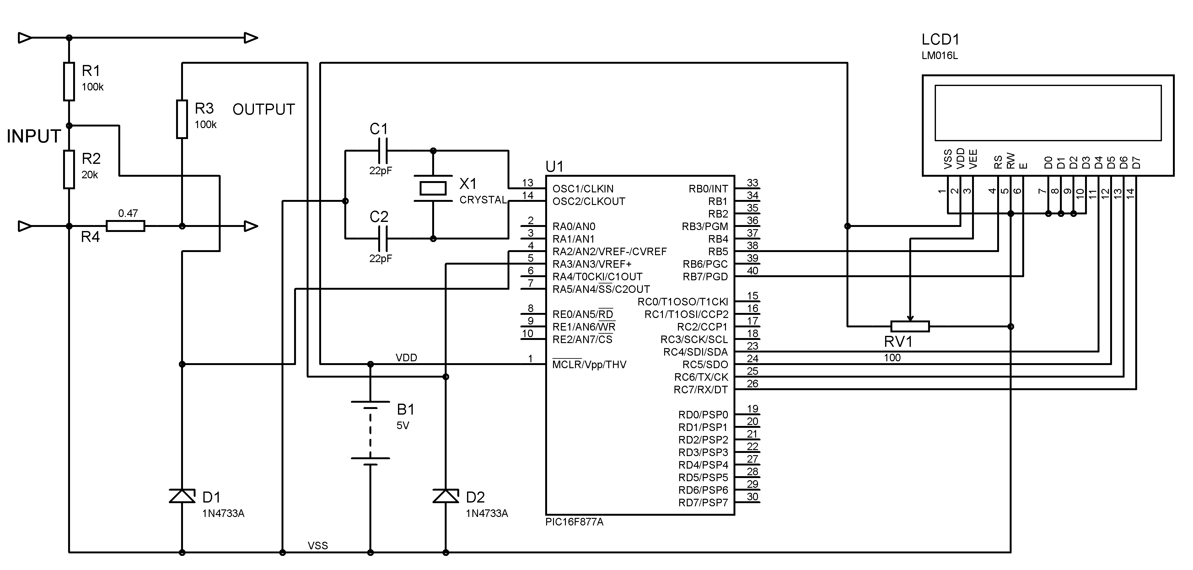
A voltmeter and ammeter can be constructed using a PIC microcontroller equipped with an Analog to Digital Converter (ADC). The project utilizes the PIC16F877A microcontroller, with results displayed on an LCD. This microcontroller is sufficient for testing purposes. For...
I don't know why, but people like blinking lights. You see LED chasers everywhere, in TV shows (Knight Rider), movies, and store windows. This schematic is my version of a simple 10 LED chaser. There is no 555 timer...
The table provided is useful for determining the capabilities of the MOSFETs across various versions. However, the connectors used in the LED3X "c" series are not rated for high continuous currents; they are technically rated for 7 amps. While...
The circuit illustrated in Fig. 1 offers a straightforward and reliable method for detecting the intensity of alternating current (AC) or extremely low frequency (ELF) fields in residential or workplace environments. It is particularly effective as it not only...
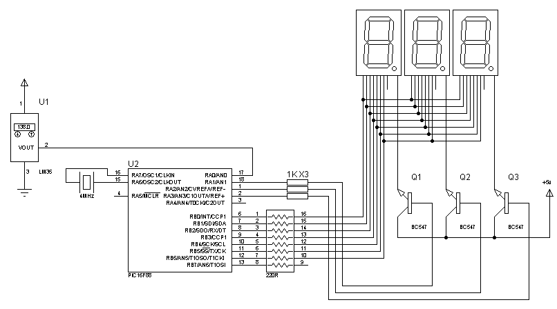
Assistance is needed to locate a schematic and code for a digital thermometer utilizing an LM35 temperature sensor and a 7-segment display, capable of measuring temperatures from 0 to 150.5 degrees Celsius. The required code must be included. The digital...