
Audio band-pass filter

A band-pass filter (BPF) is an electronic circuit that allows signals within a specified frequency range to pass through while attenuating signals outside that range. In this case, the filter is designed for a single channel with a high cutoff frequency (fH) of 50 Hz and a low cutoff frequency (fL) of 13 kHz.
The design of this band-pass filter can be implemented using passive components such as resistors, capacitors, and inductors, or through active components like operational amplifiers (op-amps) to achieve the desired frequency response. The filter's configuration may involve either a series or parallel arrangement of these components to create a frequency-selective network.
For a passive band-pass filter, a typical design might consist of a high-pass filter (HPF) and a low-pass filter (LPF) connected in series. The HPF would use a capacitor in series with the input signal and a resistor to ground, allowing frequencies above 13 kHz to pass while blocking lower frequencies. The LPF would consist of a resistor in series and a capacitor to ground, allowing frequencies below 50 Hz to pass while attenuating higher frequencies.
In an active configuration, the use of op-amps can enhance the filter's performance by providing gain and improving the filter's selectivity. The op-amp can be configured in a band-pass arrangement that utilizes feedback and external components to set the cutoff frequencies precisely.
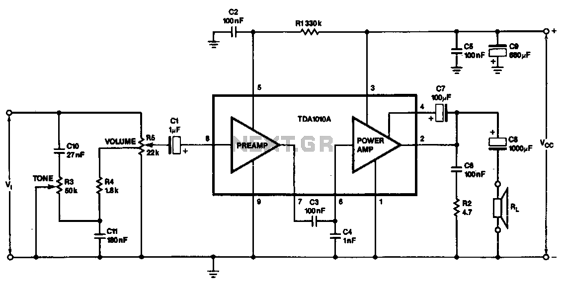
The specifications of this band-pass filter suggest it is suitable for applications where it is crucial to isolate signals within the 13 kHz to 50 Hz range, such as audio processing, communication systems, or instrumentation where unwanted frequencies must be filtered out to enhance signal clarity and integrity. Proper component selection and layout are critical to achieving the desired frequency response and minimizing distortion or noise in the output signal. Band-pass filter used for a single channel, fH 50Hz;, fl 13kHz.
Related Circuits
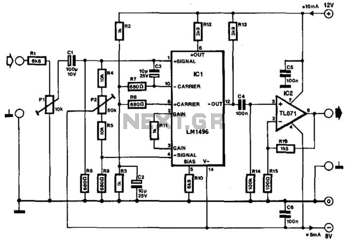
Often, the frequency of a signal must be doubled, and the modulator/demodulator chip LM1496 serves as an ideal basis for this application. From trigonometry, it is well known that 2sin(x)cos(x) = sin(2x) and sin^2(x) = 1 - cos^2(x). These...
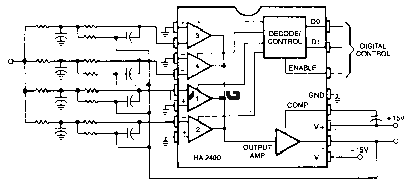
This is a second-order low-pass filter with a programmable cutoff frequency. The circuit should be driven from a low-source impedance, as there are paths from the output to the input through the unselected networks. Virtually any filter function that...
The following circuit illustrates an audio amplifier circuit diagram with a power output of 25 watts. Features include its widespread use in nearly all mass-market stereo receivers produced, providing enhanced sound quality. This audio amplifier circuit is designed to deliver...
A 183.6 MHz SAW filter is utilized in a CDMA application. The S-parameter of the SAW filter is employed to simulate the interaction with the mixer. An example is provided using the SAWTEK 855893 SAW filter. This application note...
This monolithic IC, class-B audio amplifier circuit is a 6-W car radio amplifier for use with 4-ohm and 2-ohm load impedances. The monolithic integrated circuit (IC) described is designed to function as a Class-B audio amplifier, specifically tailored for...

This is a 25-watt basic power amplifier designed for ease of construction at a reasonable cost. It offers superior performance compared to standard STK module amplifiers commonly found in most mass-market stereo receivers produced today. The 25-watt basic power amplifier...
Warning: include(partials/cookie-banner.php): Failed to open stream: Permission denied in /var/www/html/nextgr/view-circuit.php on line 713
Warning: include(): Failed opening 'partials/cookie-banner.php' for inclusion (include_path='.:/usr/share/php') in /var/www/html/nextgr/view-circuit.php on line 713