
25 watt audio amplifier circuit

The 25-watt basic power amplifier circuit is engineered to deliver reliable audio amplification while remaining cost-effective and straightforward to assemble. The design typically utilizes a complementary push-pull output stage, which enhances efficiency and linearity. The amplifier is capable of driving standard speakers with an impedance of 4 to 8 ohms, making it suitable for various audio applications.
Key components in the circuit include transistors, resistors, capacitors, and a power supply unit. The input stage often employs a differential amplifier configuration to improve signal integrity and reduce distortion. Feedback is implemented to stabilize gain and enhance bandwidth, ensuring that the amplifier maintains consistent performance across the audio spectrum.
The power supply circuit is essential for providing the necessary voltage and current to drive the output stage. It usually consists of a transformer, rectifier, and filter capacitors, which convert AC mains voltage into a stable DC supply. Proper filtering is crucial to minimize ripple voltage, which can adversely affect audio quality.
Thermal management is another critical aspect of the design. Heat sinks are typically attached to the output transistors to dissipate heat generated during operation, preventing thermal runaway and ensuring long-term reliability.
In summary, this 25-watt power amplifier circuit strikes a balance between performance, simplicity, and cost, making it an attractive option for hobbyists and those looking to build their own audio amplification solutions.This is a 25 Watt basic power amp that was designed to be (relatively) easy to build at a reasonable cost. It has better performance than the standard STK module amps that are used in practically every mass market stereo receiver manufactured today..
🔗 External reference
Related Circuits
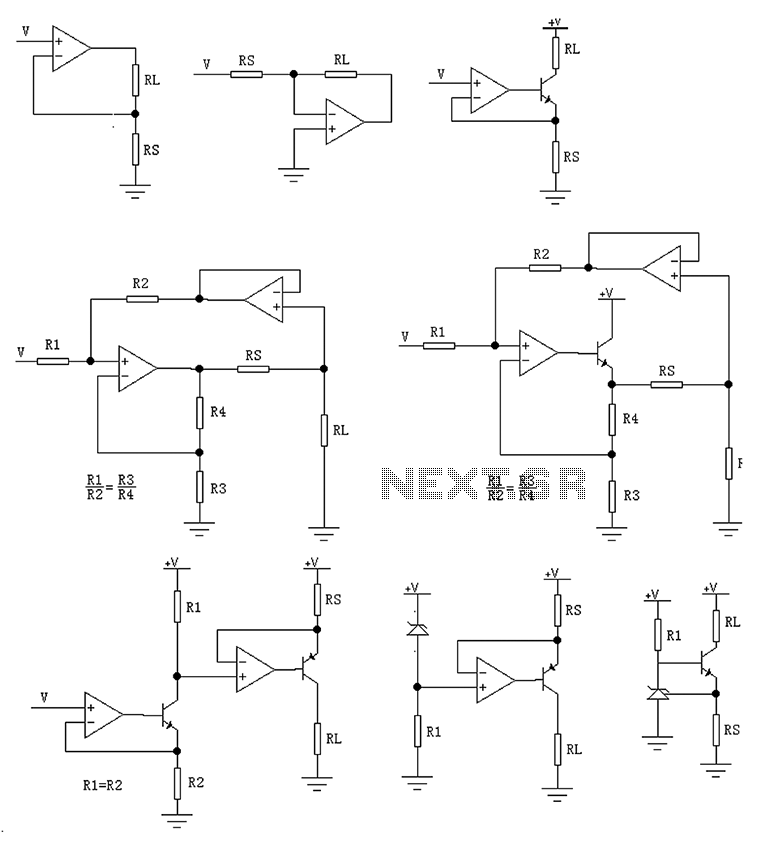
The circuit is designed to provide several constant current outputs to the load resistor RL. The first RL is floating and is rarely utilized. The second RL serves as a virtual ground and is not commonly used either. The...
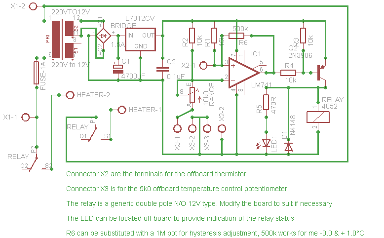
Affordable, straightforward, and precise thermostat circuits with instructions. The thermostat circuit is designed to provide a cost-effective and reliable solution for temperature control applications. It typically utilizes a temperature sensor, such as a thermistor or a thermocouple, to monitor the...
This combination sync stripper and universal video interface can solve various problems, including interfacing Super Nintendo with other devices, video overlay, and locking TV frames for scopes. Kits, fully tested units, and custom cable assemblies are available through Redmond...

This is the power diagram for motor forward and reverse operation. To change the motor direction, one polarity must be altered, for example, changing R to S. For detailed information, please refer to the following. The described power diagram illustrates...
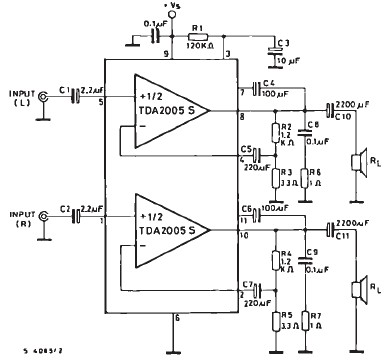
The TDA2005 car audio amplifier circuit is specifically designed for use in devices such as car radios and CD players. This amplifier circuit utilizes the TDA2005 audio integrated circuit (IC), which can deliver a maximum output power of 20...
The electronic components designed by conventional electronic bonsai create a sparkling and brilliant atmosphere in the living room, enhancing the joys and pleasures of life. The selection of components includes IC1 to IC4, which consist of two pairs of...