
Audio high-pass filter
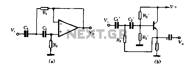
The high-pass filter depicted in Figure 1-102 serves to allow signals with a frequency higher than a certain cutoff frequency to pass through while attenuating signals with frequencies lower than the cutoff. The configuration in part (A) demonstrates a scenario where capacitor values C1 and C2 are equal, and resistor R1 is set to half the value. This results in a specific crossover frequency, calculated as fH = 1/(2√(2R1C1)). This equation indicates that the cutoff frequency is inversely proportional to the product of the resistance and capacitance values.
In part (B) of the figure, the arrangement changes slightly, with R1 being one-fourth the value of R2. Here, the relationship between the components continues to dictate the crossover frequency, which is expressed as fH = 1/(2√(R1C1)). This adjustment demonstrates how varying the resistor values can significantly impact the filter's performance and the frequency at which it begins to attenuate lower frequencies.
Design considerations for high-pass filters include selecting appropriate values for the resistors and capacitors to achieve the desired cutoff frequency, ensuring that the filter meets the specific application requirements. Additionally, the quality of the components used can affect the filter's performance, including its frequency response and signal integrity. Overall, the design and implementation of high-pass filters are crucial in various electronic applications, including audio processing, signal conditioning, and communication systems.Figure 1-102 high-pass filter in FIG. (A), and if we take C1 C2, R1 1/2, then the crossover, H 1/2 root of 2 R1C1. For Figure (b), if take C1 C2, R1 1/4R2, its crossover fH 1/2 root 2 R1 C1
Related Circuits
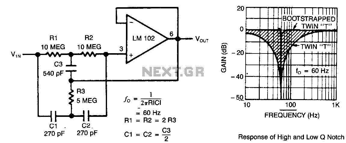
This circuit illustrates a twin-T network connected to an LM102 to form a high-Q, 60-Hz notch filter. The junction of R3 and C3, which is typically grounded, is bootstrapped to the output of the follower. Due to the low...
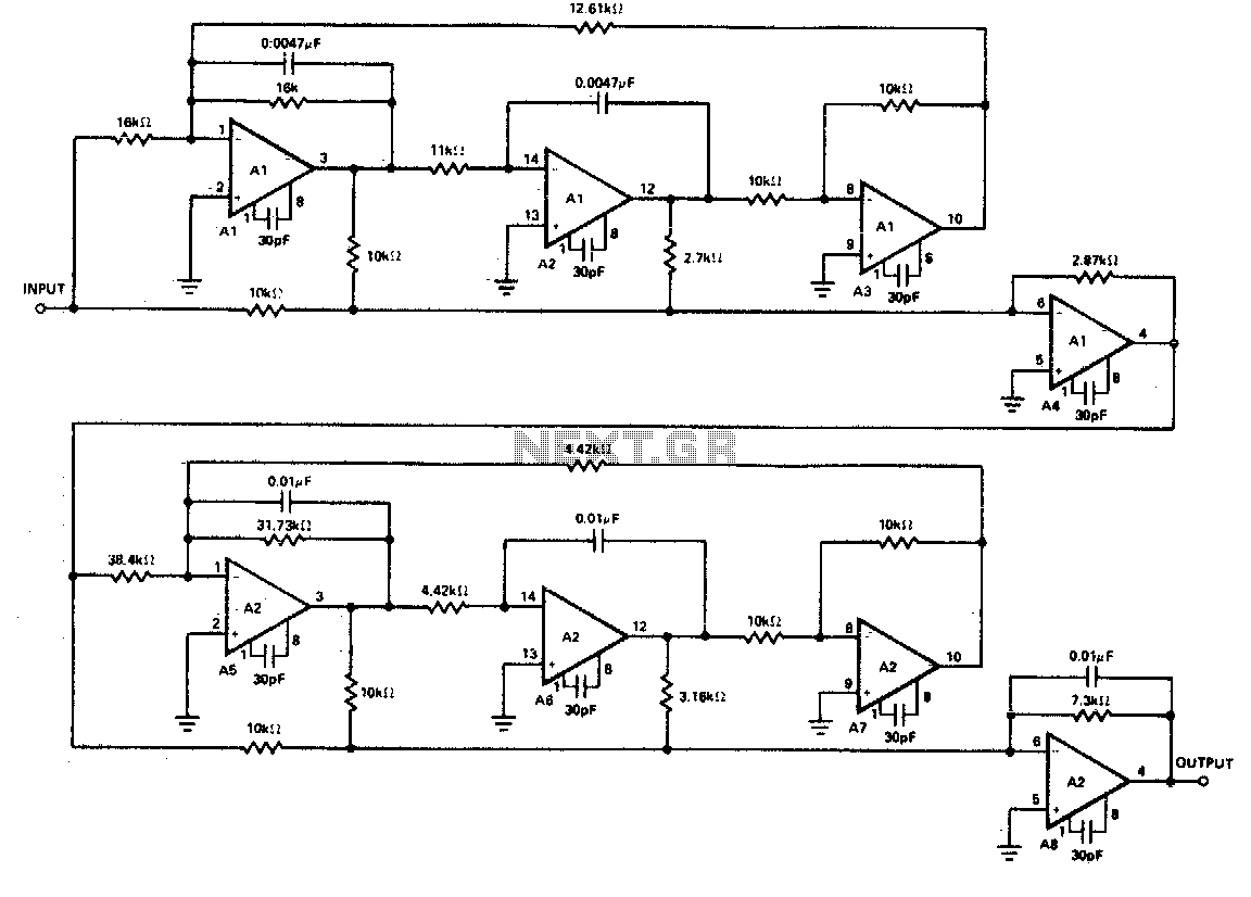
The realization of a type 03 receive filter is achieved using eight OP-08 operational amplifiers. The response curve indicates that the requirement for greater than 30 dB attenuation in the stop band has been satisfied. Furthermore, the noise performance...
This small transmitter can reach distances of more than 1 km under favorable transmission conditions. Modulation can be achieved using a microphone, such as an electret microphone, or another audio source. The transmitter includes a coil made of 5...

This circuit is an active filter designed for subwoofers, featuring a 24 dB per octave Bessel filter with a cutoff frequency of 200 Hz. It is suitable for those interested in experimenting with audio circuits in the subwoofer frequency...
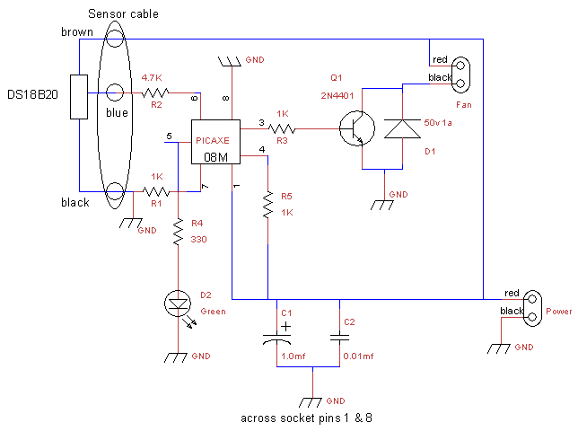
This is a fan controller designed for an audio/video cabinet. It utilizes a PICAXE 08M microcontroller and a DS18B20 temperature sensor. The fan activates at 30 degrees Celsius (approximately 86 degrees Fahrenheit) and deactivates at 28 degrees Celsius (around...
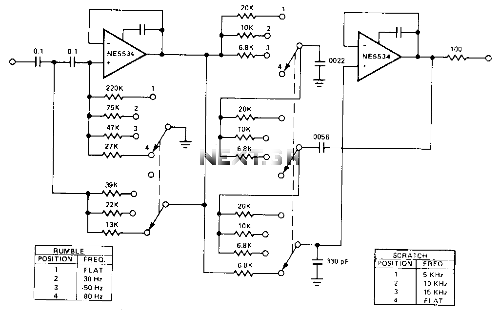
This is a variable bandpass amplifier with adjustable low and high-frequency cutoffs. A variable bandpass amplifier is designed to allow a specific range of frequencies to pass through while attenuating frequencies outside this range. The adjustable low and high-frequency cutoffs...
Warning: include(partials/cookie-banner.php): Failed to open stream: Permission denied in /var/www/html/nextgr/view-circuit.php on line 713
Warning: include(): Failed opening 'partials/cookie-banner.php' for inclusion (include_path='.:/usr/share/php') in /var/www/html/nextgr/view-circuit.php on line 713