
audio How to create a multi-extension intercom system using wired phones
To construct a basic telephone intercom system, the following components and steps are essential:
1. **Components Required**:
- Two wired telephones (preferably analog).
- A 9V battery or suitable power source.
- A resistor (typically 1kΩ) to limit current flow and protect the circuit.
- Telephone jacks (RJ-11 connectors) for neat connections.
- Cat5e cable for wiring between rooms.
- Optional: A small enclosure to house the components neatly.
2. **Wiring Configuration**:
- Each telephone will connect to the intercom system via the Cat5e cable. The cable typically consists of four twisted pairs, of which two pairs can be utilized for voice transmission.
- Connect the tip and ring wires of the telephones to the corresponding wires in the Cat5e cable. This will allow for audio transmission between the two devices.
- The resistor should be placed in series with the power supply to limit the current to the telephones, ensuring they operate within safe parameters.
3. **Intercom Operation**:
- When a user lifts the handset of one telephone, the circuit is completed, and the other telephone will ring. This is achieved through the use of a simple series connection of the components.
- To answer the call, the second user lifts their handset, which connects them to the first telephone, allowing for two-way communication.
- The system does not require complex switching mechanisms, as it is designed for straightforward operation with only two units.
4. **Installation**:
- Run the Cat5e cable from a central location (such as a living room) to each room where a telephone will be installed.
- Terminate the Cat5e cable with appropriate RJ-11 connectors at each end to facilitate easy connection to the telephones.
- Ensure that the power source is accessible and secure to prevent accidental disconnections or short circuits.
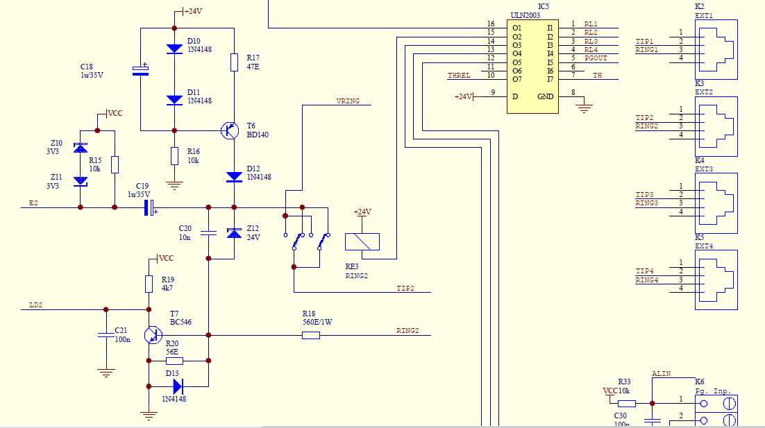
By utilizing this approach, the intercom system will provide an efficient and cost-effective solution for communication within the house, leveraging existing equipment and simple circuitry to create a functional and user-friendly intercom experience.Create a simple (telephone based) intercom system in our new house. Shouting between rooms is not so good, and trying to use an IM client or Facetime doesn`t have the immediacy of a good shout down the corridor. I`ve got a box of old wired telephones that don`t have much use any more, and will be wiring the new place with cat5e for networking so running an
extra wire to each room and sticking a phone into it is no real hassle. I`ve seen online plenty of sites showing me how to connect two phones together so you can talk in one, and it comes out the other. This seems pretty simple - a battery, a resistor, some phone jacks to make it neat. I`m not trying to create my own PBX, there`s no need to ring individual phones or have more than two people talking at once.
Picking up a handset and having all the others ring until any other handset is picked up is enough. 🔗 External reference
Related Circuits
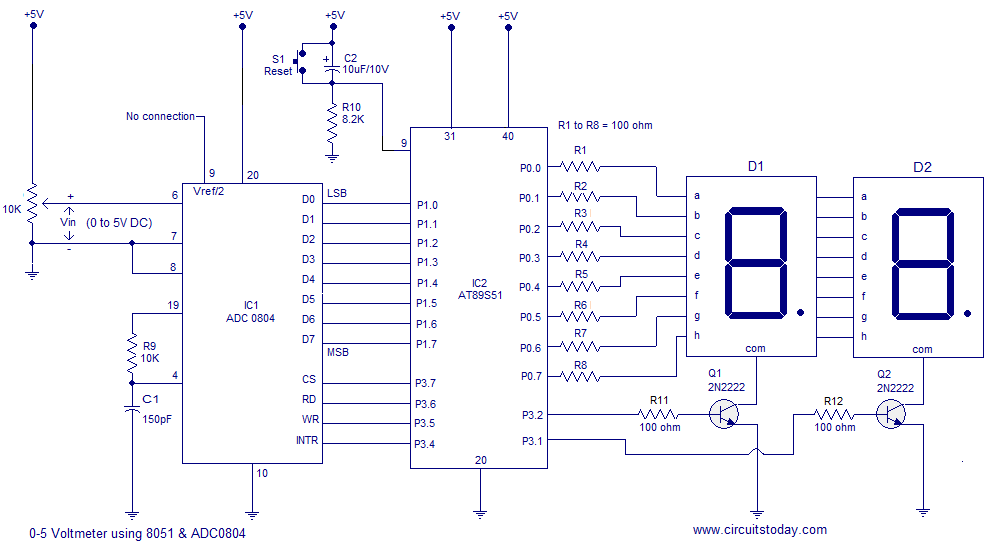
A simple 0-5 digital voltmeter utilizing the 8051 (AT89S51 microcontroller) is presented, accompanied by a circuit diagram and assembly language (ASM) code. This digital voltmeter is designed for straightforward voltage measurement. The circuit employs an AT89S51 microcontroller, which serves as...
This circuit diagram represents a remote control system utilizing DTMF (Dual Tone Multi-Frequency) signals. DTMF signals, generated by pressing numbers on a telephone keypad, serve as the control mechanism for the system. The DTMF tones are employed to modulate...
The circuit diagram is designed to control audio tone. This circuit utilizes the TDA 1524 tone control integrated circuit (IC), which encompasses controls for balance, bass, treble, and volume within a single component. A potentiometer is employed in series...
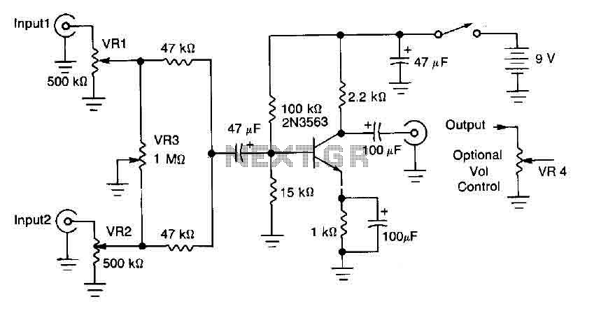
This circuit mixer features internal amplification using a 2N3563 transistor. Two input signals can be independently adjusted via VRI and VR2. The VR3 balance control allows for the attenuation of one signal while the other remains active. Additionally, the...
That circuit will provide an overall gain of one between the output and each input channel. Each input channel includes a single 0.1uf capacitor and 100-Kilohms resistor to provide an output impedance of 100K. The number of input channels...
Integrated AF power amplifiers have experienced significant advancements in recent years, offering enhanced power and ease of use. The TDA1519C from Philips features two power amplifiers that provide 11 W per channel in stereo mode or 22 W in...