
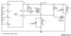
Audio level meter using LM3915
The analog VU meter operates on the principle of integrating the audio signal over a defined period, providing an average representation of the signal level rather than instantaneous peaks. The design typically includes a magnetoelectric movement, which is sensitive to the audio signal's voltage changes. As the audio signal passes through the meter, it generates a magnetic field that moves a needle across a calibrated scale.
The inclusion of a peak LED serves as an additional feature, allowing users to visually monitor peak signal levels, which can be critical for preventing distortion during audio recording and playback. The slow response time of the VU meter, characterized by its 300-millisecond rise and fall times, makes it particularly suitable for monitoring program material that has a dynamic range, such as music and speech, rather than fast transient signals.
In practical applications, the VU meter is often integrated into mixing consoles, audio interfaces, and various audio processing equipment. The typical layout of the VU meter includes a scale marked in decibels (dB), where the zero reference point corresponds to 0 VU. The scale generally extends from -20 dB to +3 dB, providing a clear visual representation of the audio signal's amplitude relative to the reference level.
The VU meter's functionality is essential in professional audio environments, as it aids engineers and producers in achieving optimal levels during mixing and mastering processes. Despite its limitations in peak level measurement, its ability to reflect perceived loudness makes it a valuable tool in the audio engineering toolkit.An analog VU meter is often included in the audio equipment to display signal levels in volume units. Analog VU meters with peak LED Another Thumbnail magnetoelectric VU meter response of a VU meter (black line) compared with the instantaneous input level (gray areas) of a drum beat.
Level in dB and the time in seconds VU electric meterIt is inte ntionally a slow measurement, the average of peaks and valleys of short duration to reflect the material considered loudness. It was originally developed in 1939 by a joint effort of Bell Labs and Broadcaster CBS and NBC to measure and standardize the level of the phone line.
The instrument used to measure the volume of VU-called indicator (VI) instrument. Most users ignore this and call it a VU meter. The following is a schematic drawing: VU typical scale is from -20 to +3. The rise and fall times of both 300 meters milliseconds, which means that if a constant sine wave of amplitude 0 VU is applied suddenly, the 300 meters will take milliseconds to reach 0 on a scale. Behaves as a full-wave instrument on average, and not optimal to measure the peak level. 🔗 External reference
Related Circuits
This circuit is designed to indicate the power output level of any audio amplifier. It is simple, portable, and displays three power levels that can be set to any desired value. The circuit operates by utilizing a combination of resistive...
Circuit stereo TDA2822 audio power amplifier circuit schematics. In this series, the TDA2822M IC is utilized as the primary amplifier. Additionally, alternatives such as KA2209 and NJM2073 can also be employed. The TDA2822 audio power amplifier circuit is designed to...
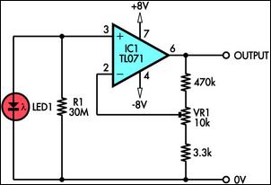
This circuit demonstrates the use of a standard LED as a light sensor. It utilizes the photovoltaic voltage generated across the LED when exposed to light. LEDs are more cost-effective than photodiodes and feature an integrated filter, which is...
The device employs a microammeter with a full-scale deflection of 50 µA and a resistance of 2 kilohms. The upper limit of the voltmeter's measuring range is 1 V, and within the range of 0.2 to 1 V, the...
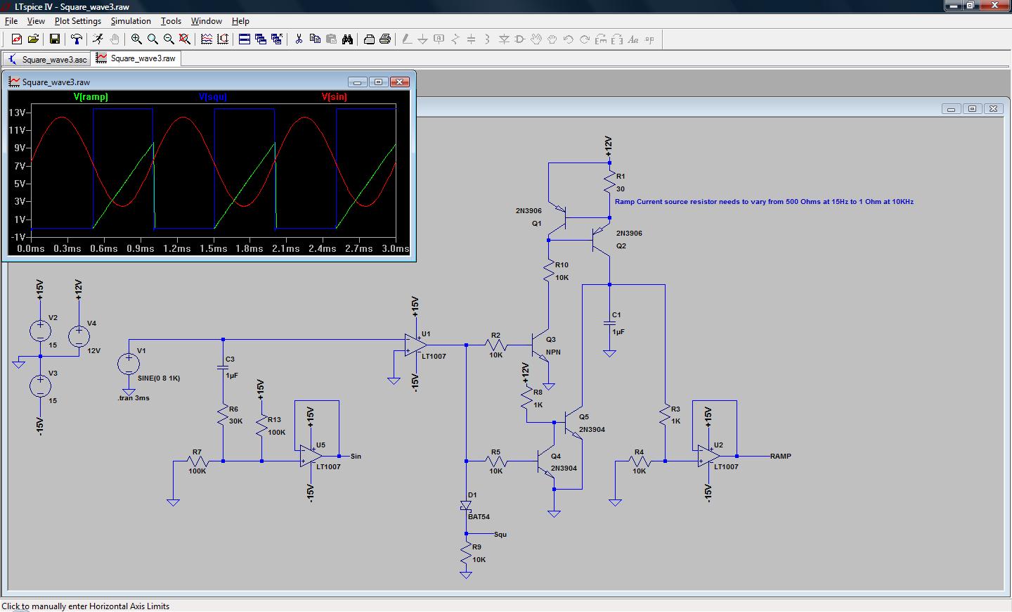
A simple low-end audio function generator is being designed to utilize a sine wave output for testing ADC resolution and as a baseband signal for RF projects, with an emphasis on achieving very low total harmonic distortion (THD). The...
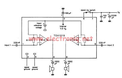
The TDA1519 circuit can deliver 2x6 watts output power. TDA1519 is an integrated class-B dual output amplifier in a 9-lead single in-line (SIL) plastic medium power package primarily developed for car radio applications. The TDA1519 is a robust integrated circuit...