
Audio oscillator
The Wien bridge oscillator is a precision waveform generator widely used in audio and signal processing applications. Its design is based on a bridge configuration that employs resistive and capacitive components to establish a frequency-dependent condition for oscillation. The key to its operation lies in maintaining a balance between the resistive and capacitive elements to achieve a specific phase shift that is essential for sustained oscillation.
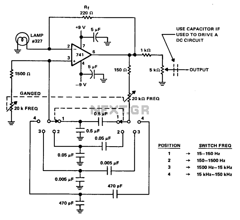
The oscillator operates with a feedback mechanism that adjusts the gain dynamically. The use of a small lamp, which has a positive temperature coefficient, allows for self-regulation of the gain. As the output amplitude increases, the temperature of the lamp rises, leading to an increase in its resistance. This, in turn, reduces the gain, preventing distortion and ensuring that the loop gain remains at unity at the desired oscillation frequency.
The four frequency bands enable a wide range of applications, from low-frequency signal generation to high-frequency test signals. The ganged 20 k ohm potentiometers provide fine control over the frequency settings, allowing for smooth transitions across the frequency range. The current draw of 4.0 mA from the 9-V power supply indicates efficient operation, making it suitable for battery-powered applications.
The output characteristics of the oscillator are designed to deliver a stable sine wave with an amplitude of 4 to 5 V under a 10 k ohm load, making it compatible with various electronic circuits. The feedback resistor (Rf) is crucial in determining the clipping point, and setting it slightly below this threshold ensures that the output waveform remains undistorted.
For applications that require interfacing with DC circuits, the inclusion of a coupling capacitor is essential. This capacitor blocks any DC offset present in the output, allowing only the AC component of the signal to pass through, thus protecting downstream components from potential damage caused by DC levels.
Overall, the Wien bridge oscillator is a versatile and reliable circuit for generating low-distortion sine waves across a broad frequency spectrum, with features that enhance its usability in various electronic applications.A Wien bridge oscillator produces sine waves with very low distortion level. The Wien bridge oscillator produces zero phase shift at only one frequency (f = Vx t RC) which will be the oscillation frequency. Stable oscillation can occur only if the loop gain remains at unity at the oscillation frequency. The circuit achieves this control by using the positive temperature coefficient of a small lamp to regulate gain (Rf/RLAMp) as the oscillator attempts to vary its output.
The oscillator shown here has four frequency bands covering about 15 Hz to 150 kHz. The frequency is continuously variable within each frequency range with ganged 20 k ohm potentiometers. The oscillator draws only about 4.0 mA from the 9-V batteries. Its output is from 4 to 5 V with a 10 k ohm load and the Rf (feedback resistor) is set at about 5% below the point of clipping.
As shown, the center arm of the 5 k ohm output potentiometer is the output terminal. To couple the oscillator to a dc type circuit, a capacitor should be inserted in series with the output lead. 🔗 External reference
Related Circuits
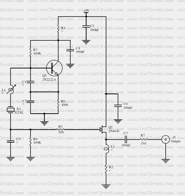
This crystal oscillator is designed to operate with fundamental crystals with less than 1 mW dissipated in the crystal. The signal current is filtered by the crystal and develops a voltage across a capacitor with about 500 ohm of...
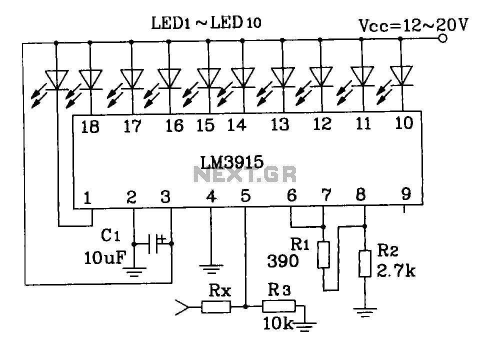
This document describes a simple LM3915 audio power meter circuit diagram. It notes that if the internal resistance of the speaker is 4 ohms, a resistor value of 10k ohms should be used for Rx. For an 8-ohm speaker,...
The audio source will be a line-level audio signal ranging from -2V to +2V AC, which will be passed through a 220µF coupling capacitor followed by a two-pole low-pass filter (RC). The signal will be processed by an Analog-to-Digital...
This circuit is intended to indicate the power output level of any audio amplifier. It is simple, portable, and displays three power levels that can be set to any desired value. IC1A is the input buffer, feeding 3 voltage...
The following diagram illustrates the circuit of a Stereo OTL Audio Amplifier. It is based on an integrated circuit (IC), making the circuit design straightforward. The amplifier project can utilize ICs such as LM379, LM377, or LM378. According to...
The circuit is based around LM4702 manufactured by NATIONAL semiconductors MJ11029-MJ11028 by ON semiconductors. It is a high fidelity audio power amplifier designed for demanding consumer and pro-audio applications. You can also use this circuit with AV receivers, audiophile...