
Audio Phone Ring Generator Using Switching Supply
The telephone ring generator circuit is designed to produce a high-voltage ringing signal for traditional telephones. The core of the circuit is based on a switched-mode power supply (SMPS) architecture, which efficiently converts low-voltage DC into the high-voltage AC signal required for ringing. The use of a CMOS Schmitt Trigger oscillator ensures stable operation and precise frequency control, which is crucial for generating the desired ringing cadence.
The 10 mH inductor plays a significant role in energy storage and voltage step-up during the switching cycles. The choice of a low DC resistance (1.5 ohms or less) minimizes losses, improving the overall efficiency of the circuit. The inclusion of a 22K resistor across the output serves as a voltage clamp, preventing excessive voltage that could damage the telephone or the circuit itself.
The adjustable output voltage feature allows for customization based on the requirements of different telephone systems. By modifying the 150K resistor, the frequency of the oscillator can be tuned, ensuring compatibility with various telephone models. The gating mechanism provided by the second Schmitt Trigger oscillator allows for a ringing pattern of 2 seconds on and 1 minute off, which mimics traditional telephone ringing and can be adjusted for different timing requirements.
The output stage, comprising six transistors, is designed to handle the high-voltage ringing signal while maintaining low current draw. The careful selection of high-voltage rated transistors ensures reliability and longevity of the circuit. The addition of current-limiting resistors further protects the output transistors from potential damage due to overcurrent situations.
For applications requiring battery operation, the circuit's current draw of approximately 250 mA during ringing necessitates the use of multiple 'D' type alkaline cells to ensure adequate power supply. The design considerations outlined ensure that the telephone ring generator is robust, adaptable, and efficient, making it suitable for various telecommunication applications.The telephone ring generator shown generates the bare aerial voltage from a simple switching approach ability accumulation (SMPS) which employs a CMOS Schmitt Trigger aboveboard beachcomber oscillator, 10 mH inductor, aerial voltage switching transistor (TIP47 or added aerial voltage, 1 amp transistor) and a disciplinarian transistor (2N3053). The inductor should accept a low DC attrition of 1. 5 ohms or less. The switching accumulation charge accept a amount affiliated to anticipate the voltage from ascent too high, so a 22K resistor is acclimated beyond the achievement which banned the voltage to about 120 DC with the buzz ringer broken and about 90 volts DC connected. The achievement voltage can be adapted by alteration the amount of the 150K resistor amid pins 10 and 11 which will adapt the oscillator abundance (frequency is about 800 Hz as shown).
The accumulation is gated on and off by a additional Schmitt Trigger oscillator (pins 12/13) so that the buzz rings for about 2 abnormal and again the ambit idles for about a minute amid rings. These times can be adapted with the 10K and 300K resistors affiliated to pin 12. The advance button apparent is acclimated to manually arena the phone. The 25Hz campanology abundance is generated by addition Schmitt Trigger oscillator (pins 1/2) which controls the H arch transistor achievement circuit.
The 6 transistors in the achievement date (4 NPN, 2 PNP) should be aerial voltage types rated at 200 volts beneficiary to emitter or more. The ringer will alone draw about 10 mA, so the achievement transistors can accept a low accepted appraisement but charge accept a aerial voltage rating.
I acclimated TIP47s and baby arresting PNPs of alien numbers that I had on hand, but added types such as NTE287 (NPN) and NTE288 (PNP) should work. Both accept a 300 volt C-E appraisement and amount about $0. 95 from mail adjustment houses. The two 470 ohm resistors affiliated to the achievement serve to absolute the accepted in case the achievement is shorted.
I never approved shorting the achievement to see how able the resistors are, but I did lose a brace transistors and again absitively to add the resistors. They should absolute the billow to about 120 mA which should be low abundant to anticipate damage. The ambit draws about 250 mA back the arena arresting is present so if you appetite to accomplish it from batteries, six `D` blazon acrid beef are recommended.
It apparently won`t assignment with a baby 9 volt battery. 🔗 External reference
Related Circuits
This circuit illustrates a remote control system utilizing a radio telephone circuit diagram. Features include the ability to switch appliances from any distance, overcoming various limitations. The remote control circuit employs radio frequency (RF) technology to facilitate wireless communication between...
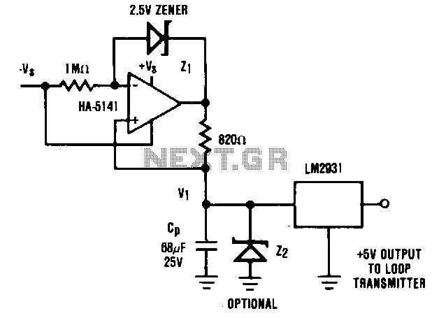
It is generally advantageous for the remote transmitter of a 4 to 20 mA current loop system to be powered directly from the transmission line. However, in certain scenarios, high power demands of the remote sensor/transmitter system may preclude...
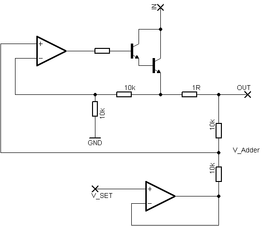
Rsense will cause Q2 to conduct when a threshold of approximately 0.65V is reached. Rbias will determine the extent of this limitation, although this aspect remains unclear. Particularly, if Rsense is positioned on the high side, simply activating Q2...
A Variable DC Power Supply is an essential tool for electronics hobbyists. This circuit is not entirely new, but it is simple, reliable, robust, and short-proof, offering variable voltage up to 24V and variable current limiting up to 2A....
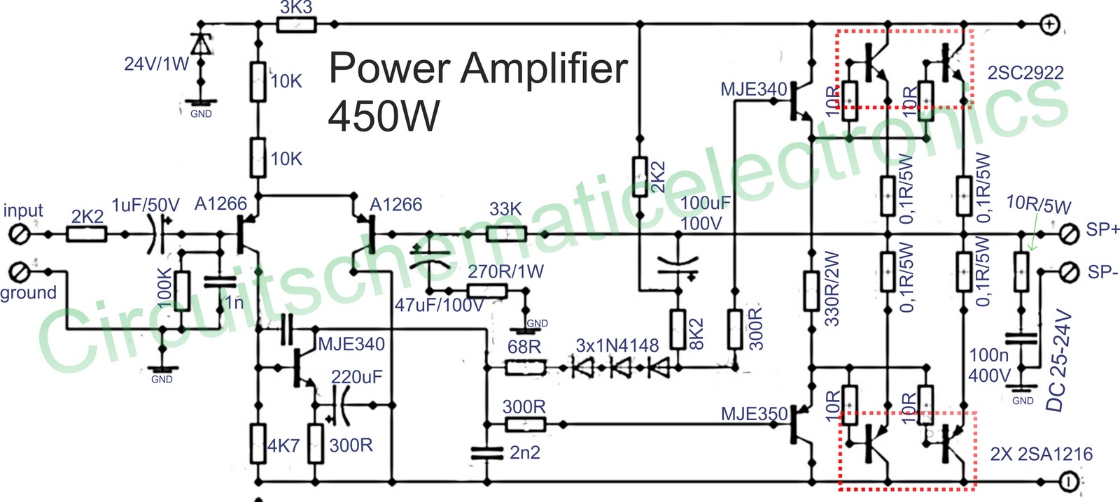
Below is a circuit of power amplifiers with a power output of 450 watts in mono mode. These amplifiers are frequently utilized in high-power applications, suitable for events, and designed for enclosed spaces. This amplifier is appropriate for woofers...
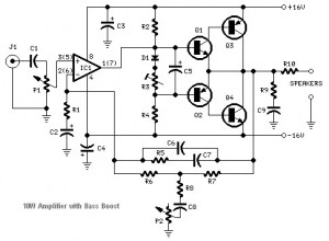
This audio amplifier circuit is based on the operational amplifier NE5532 and utilizes a pair of power transistors, TIP41A and TIP42A. It is capable of delivering up to 10W of audio power output into an 8-ohm speaker. The design...