
Audio Power Amplifier 60W with TDA7294 circuit
The TDA7294 amplifier module is optimized for audio applications requiring high fidelity and efficiency. Its monolithic design simplifies integration into various audio systems. The capability to drive both 4-ohm and 8-ohm speakers makes it versatile for different speaker configurations. The specified output of 50W RMS at 8 ohms with low distortion is suitable for high-quality audio reproduction, making it ideal for home theater systems, musical instrument amplifiers, and public address systems.
The thermal management of the TDA7294 is critical for reliable operation. The requirement for a heatsink rated at 1.4 °C/W indicates the need for effective heat dissipation, particularly under high load conditions. The internal thermal protection features add a layer of safety, preventing damage due to overheating by muting the output and transitioning to standby mode at specified temperature thresholds.
Wiring considerations include ensuring that the MUTE and STANDBY pins are appropriately managed to avoid unwanted noise during power-up. The suggested modifications to the timing components (R3-C6 and R4-C5) can further refine the power-on behavior of the amplifier, enhancing user experience by minimizing audible artifacts.
In terms of power supply design, the recommendation to use a transformer rated at a minimum of 80VA ensures that the module operates within its safe limits, providing sufficient current without risking voltage drops that could affect performance. For stereo applications, the increase to a 150VA transformer ensures that both channels receive adequate power, maintaining sound quality and dynamic range.
Overall, the TDA7294 amplifier module is a robust solution for high-fidelity audio amplification, requiring careful attention to thermal management and power supply specifications to achieve optimal performance.The TDA7294 amplifier module is a monolithic integrated circuit. It is intended for use as an audio class AB amplifier in hi-fi applications. It has a wide voltage range and output current capability, enabling it to supply the highest power into both 4 ohm and 8n ohm loads. With the addition of a handful of parts and a suitable power supply, this module will deliver 50W RMS into 8-ohm with 0. 1% THD. you the user must supply a heavy duty heatsink rated at 1. 4 °C/W. Pin 10 is the MUTE input and pin 9 provides a STANDBY mode. Muting should always take place before standby mode is selected. Connecting these pins permanently to the supply rail (insert links) ensures that the amplifier comes on immediately on power up. Increasing the time constants R3-C6 and R4-C5 may eliminate any switch-on clicks. The IC has internal thermal protection that causes the mute to cut in at 145 °C and switches the amplifier into standby at 150 °C.
Do not operate the module without a heatsink. The heatsink tab on the TDA7294 IC is internally connected to the negative supply rail. If the module is mounted inside an earthed metal enclosure then the IC must be insulated from the heatsink. If not, the negative supply rail will be shorted to ground. The maximum supply voltage of the IC is +/-40V. However the maximum dissipation of the IC would be exceeded when using a 4-ohm load at that voltage. Therefore the supply voltage used should be kept down to a safe +/-30V. The mains transformer used to power the module should be rated at a minimum of 80VA. If you want to run two modules in a stereo amplifier you can use a common power supply. In this case the transformer should be rated at 150VA. 🔗 External reference
Related Circuits
The LM317 is an adjustable, positive 3-terminal voltage regulator capable of supplying 100 mA (for RA87U control) or 1.5 A (for Order Code UF27E and N61CA) across an output voltage range of 1.2 V to 37 V. These voltage...
Schematic and description of a simple and easy-to-build NiCd and NiMH battery charger circuit that is capable of charging multiple NiCd and NiMH batteries. The circuit for the NiCd and NiMH battery charger is designed to be straightforward, allowing for...
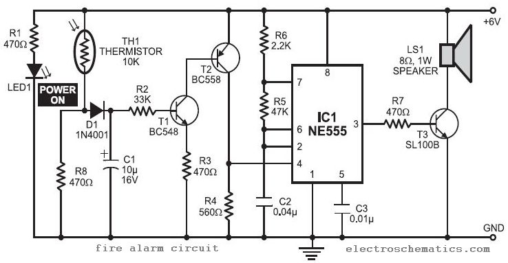
In this fire alarm circuit project, a thermistor functions as the heat sensor. When the temperature rises, its resistance decreases, and conversely, when the temperature falls, its resistance increases. Under normal conditions... In this fire alarm circuit, the thermistor is...
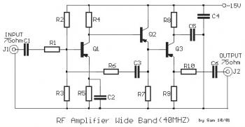
This is a 40 MHz RF amplifier circuit. The sensitivity of a receiver can be significantly enhanced by integrating this circuit between the receiver and the antenna. The amplifier does not utilize resonant circuits and is suitable for both...

Power Amplifier Speaker Protection Circuit Schematic. When a power amplifier is switched on, a loud thump sound is often heard due to a sudden heavy discharge. The power amplifier speaker protection circuit is designed to prevent loud thump sounds during...
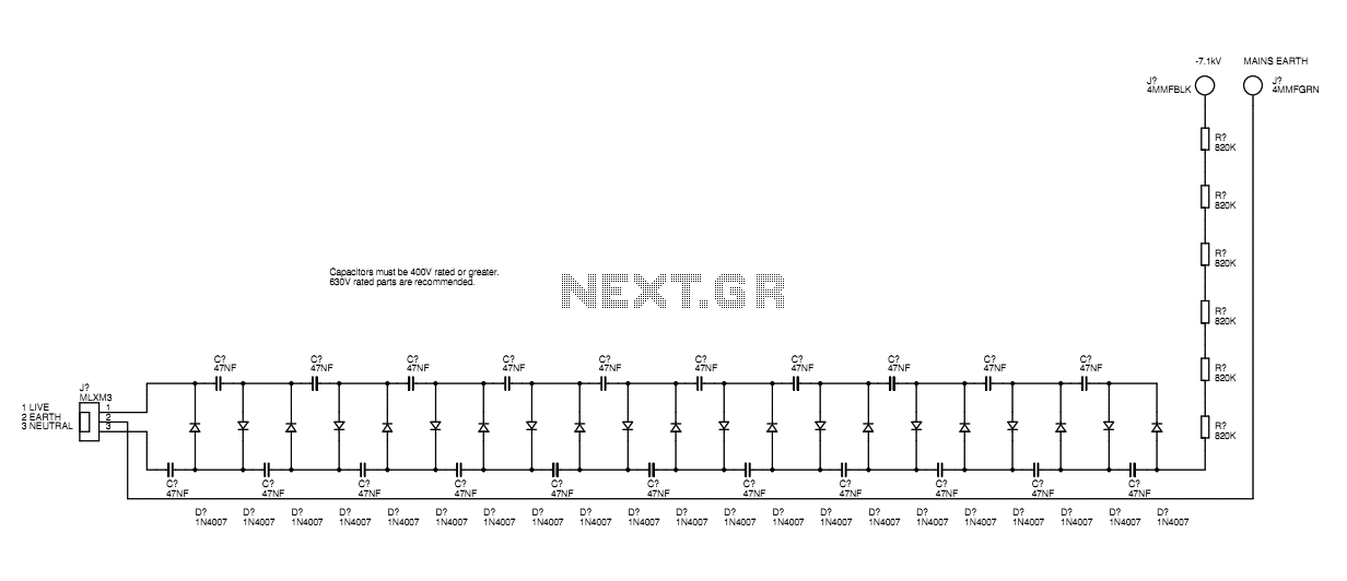
A basic mains driven Cockroft ladder high voltage generator is shown in the schematic. This is functionally the same as a project in Electronics Today International many years ago. The peak mains voltage of 340V appears across each capacitor...
Warning: include(partials/cookie-banner.php): Failed to open stream: Permission denied in /var/www/html/nextgr/view-circuit.php on line 713
Warning: include(): Failed opening 'partials/cookie-banner.php' for inclusion (include_path='.:/usr/share/php') in /var/www/html/nextgr/view-circuit.php on line 713