
Power Amplifier Speaker Protection Circuit Schematic

The power amplifier speaker protection circuit is designed to prevent loud thump sounds during the power-up sequence of an amplifier, which can potentially damage speakers. This circuit typically employs a relay-based design that disconnects the speakers from the amplifier output during the initial power-up phase.
The schematic generally includes the following components: a relay, which acts as a switch to connect or disconnect the speakers; a delay timer circuit, which ensures that the relay remains open for a brief period after the amplifier is powered on; and a protection diode that prevents back EMF from the relay coil from damaging other components in the circuit.
Upon powering the amplifier, the delay timer circuit is activated, allowing a short time for the amplifier to stabilize. During this period, the relay remains in the open position, isolating the speakers from the output. Once the timer completes its cycle, the relay is energized, closing the circuit and connecting the speakers to the amplifier output. This sequence effectively eliminates the loud thump sound, providing a safer operation for both the amplifier and the connected speakers.
The use of high-quality components is essential to ensure reliability and performance. Additionally, the circuit may incorporate indicator LEDs to show the status of the relay operation, enhancing user feedback. Overall, this protection circuit is a crucial addition to any power amplifier design, safeguarding against potential audio transients that could harm speaker systems.Power Amplifier Speaker Protection Circuit Schematic While switching a power amplifier on, a loud thump sound is heard to sudden heavy discharge.. 🔗 External reference
Related Circuits
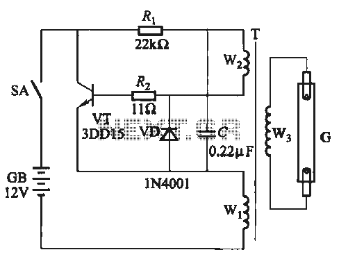
A self-excited transistor inverter circuit is designed for improved performance and features a relatively simple schematic. It is suitable for driving fluorescent lamps with a power rating between 8 to 40 watts. This inverter can operate stably even when...
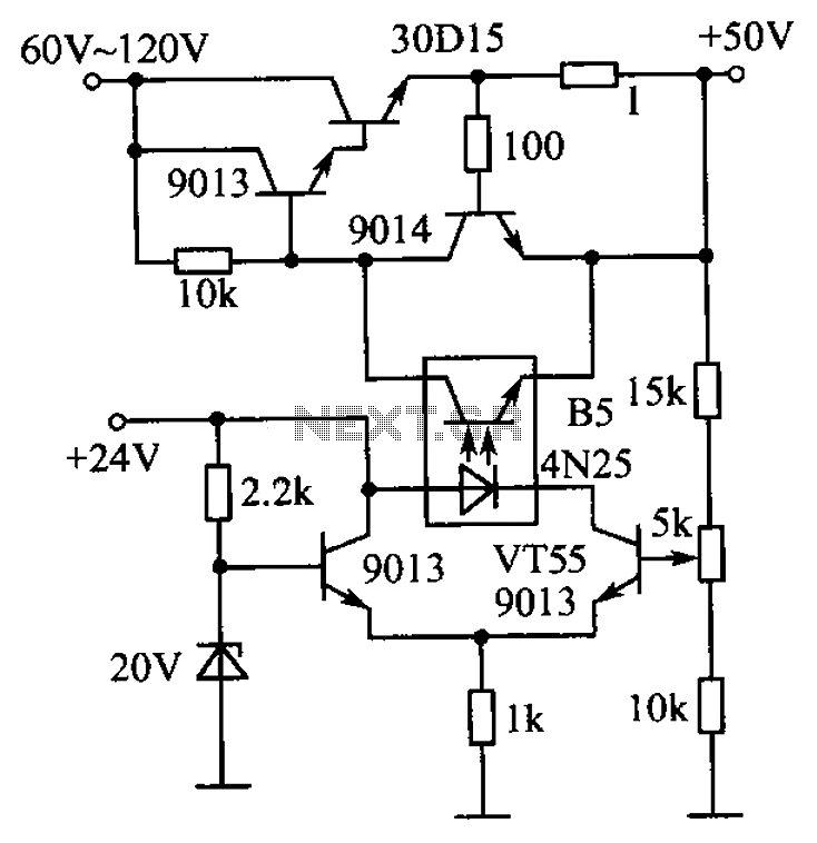
The circuit is illustrated. A standard driving transistor requires a higher breakdown voltage transistor (such as the FIG driving tube 9013). As the output voltage rises, the bias on VT55 increases, leading to an increase in the forward current...
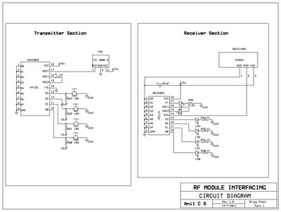
This document presents a circuit example for interfacing an RF module using the HT12E/D encoder-decoder pair. The attached circuit can be utilized for data transmission via the RF module, which is designed for single-channel operation, allowing only serial data...
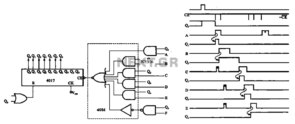
An asynchronous counter is illustrated in this circuit. It operates without a clock synchronization signal, making it suitable for use in a random counter or as an independent unit circuit. An asynchronous counter, also known as a ripple counter, is...
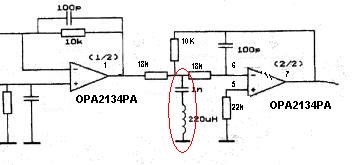
Can someone explain why there is an LC filter in the op-amp circuit? Additionally, are there any modifications that can be made to enhance the sound quality? The presence of an LC filter in an operational amplifier (op-amp) circuit serves...
This LM338-based power supply can deliver approximately two outputs of 12 to 36 volts at 5 amps each (10 amps in version 2 of this power supply, which includes transistors to increase the current capacity). The design utilizes two...
Warning: include(partials/cookie-banner.php): Failed to open stream: Permission denied in /var/www/html/nextgr/view-circuit.php on line 713
Warning: include(): Failed opening 'partials/cookie-banner.php' for inclusion (include_path='.:/usr/share/php') in /var/www/html/nextgr/view-circuit.php on line 713