
Audio preamplifier circuits
Audio preamplifiers are essential components in audio signal processing, serving to amplify low-level audio signals before they are fed into power amplifiers or other processing equipment. The following details outline three unique preamplifier circuits, with a particular focus on the intercom preamp.
The intercom preamp circuit is designed to enhance audio signals transmitted between intercom units. It typically consists of a low-noise operational amplifier (op-amp) configured in a non-inverting configuration to ensure minimal signal distortion and high input impedance. This configuration allows the circuit to accept signals from various audio sources, such as microphones or audio playback devices.
Key components of an intercom preamp may include resistors for setting the gain, capacitors for coupling and decoupling signals, and possibly a power supply circuit to ensure stable operation. The gain of the preamp can be adjusted by varying the feedback resistor values, allowing customization based on the specific requirements of the intercom system.
Additionally, the circuit may incorporate filtering stages to eliminate unwanted noise and enhance signal clarity, ensuring that the audio output is clear and intelligible. Proper grounding and layout considerations are crucial in minimizing electromagnetic interference, which can degrade audio quality.
In summary, the intercom preamp circuit exemplifies a practical application of audio preamplification, showcasing the importance of circuit design in achieving high-quality audio signal transmission in intercom systems.Electronics Circuits Reference Archive Audio preamplifier circuits There are thousands of pre-amplifier circuits. These are three which have interested me and are a little different. Intercom preamp A very convenient way of making an interc.. 🔗 External reference
Related Circuits
As shown in the figure, the 555 timer, resistors R1, RP1, and capacitor C1 form a controlled audio oscillator. The frequency of the oscillator is given by the formula f = 1.44 / ((R1 + 2 * RP1) *...
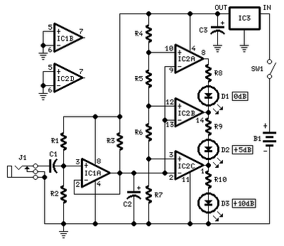
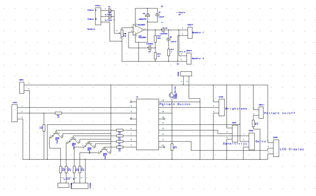
No setup is required: if correct values are used for resistors R3 to R7, LED D1 will illuminate at 0 dB input (0.775V RMS), LED D2 at +5 dB input (1.378V RMS), and LED D3 at +10 dB (2.451V...
This circuit is used to convert a mono audio signal into a stereo signal that can be panned between the left and right channel by a 0-10V control signal, it is intended for analog synthesizer systems. The circuit design focuses...
The hardware within this circuit involves a Picaxe 18M2 integrated circuit, which serves as the programmable microcontroller in the design and can be programmed using a PC. The Picaxe 18M2 microcontroller is a versatile device that is well-suited for a...
Most universal radio receivers have a very wide bandwidth that is not particularly suitable for radio amateurs. The better models with narrower bandwidth are almost a... Universal radio receivers are designed to operate over a broad frequency range, making them...
When the amplifier is installed inside the suitcase, it will require a change to stop working. The LA47536 has a control pin (pin 4) that requires a small voltage of up to 2V to turn on the amplifier. Transistors...
Warning: include(partials/cookie-banner.php): Failed to open stream: Permission denied in /var/www/html/nextgr/view-circuit.php on line 713
Warning: include(): Failed opening 'partials/cookie-banner.php' for inclusion (include_path='.:/usr/share/php') in /var/www/html/nextgr/view-circuit.php on line 713