
Audio splitter

The circuit operates as an audio distribution amplifier, designed to enhance and distribute audio signals across multiple outputs. The input audio signal is connected through a jack (J1), which serves as the entry point for the audio source. This signal is then routed to a potentiometer (P1), which allows for adjustable gain control, enabling the user to set the desired level of amplification before the signal is processed further.
Following the potentiometer, the signal is fed into an operational amplifier (U1). This component is crucial as it buffers the audio signal, preventing loading effects that could degrade the audio quality. The operational amplifier is configured to provide gain, effectively amplifying the input signal to a suitable level for distribution. The choice of the operational amplifier should consider factors such as bandwidth, noise performance, and power supply requirements to ensure optimal audio fidelity.
After amplification, the circuit features three output ports designed to drive audio lines, each with an output impedance of 300 ohms. This impedance is standard for many audio applications, allowing compatibility with various audio equipment, such as speakers or additional amplification stages. The outputs are typically connected to audio cables that transmit the amplified signal to the intended destinations.
The overall design of the circuit emphasizes low distortion and high fidelity, making it suitable for professional audio applications where signal integrity is paramount. Proper layout and shielding techniques should be employed in the physical implementation to minimize interference and maintain signal quality, particularly in environments with potential electromagnetic noise. Power supply decoupling capacitors may also be included near the operational amplifier to ensure stable operation and reduce noise from the power supply.This circuit is suitable to amplify and distribute the audio signals. The input audio signal is applied to the J1 and after passing through the P1, It is buffered and amplified by the U1 prepared to redistribute. It has 3 output to drive 3 audio lines with 300 ohms impedance. 🔗 External reference
Related Circuits
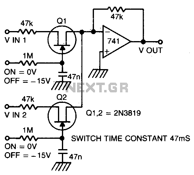
Two or more signals can be switched and/or mixed without annoying clicks by using FETs and a low input-impedance op amp circuit. The circuit design utilizes Field Effect Transistors (FETs) to facilitate the switching and mixing of multiple signals while...
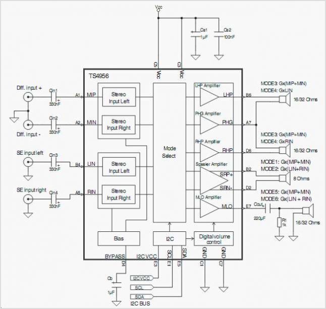
The TS4962 is a differential class-D BTL power amplifier capable of driving up to 2.2W into a 4-ohm load and 1.4W into an 8-ohm load at 5V. It achieves outstanding efficiency (typical 88%) compared to standard AB-class audio amplifiers....
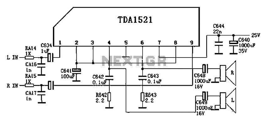
Color is often used in audio circuits like the TDA1521, which is derived from the Changhong C2191 model featuring an OTL two-channel connection. The pin functions and reference voltages for the TDA1521 are as follows: Pin 1: 11V -...
This is a compact and portable unit that can be constructed on a veroboard. The amplifier's gain is nominally set at 20 dB, and its frequency response is primarily dictated by the component values used. The design of the amplifier...
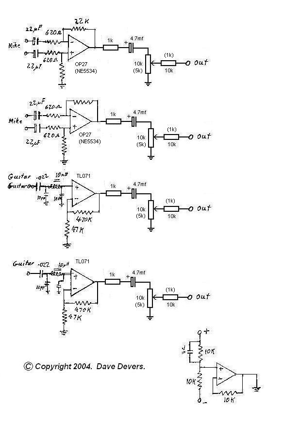
The mixer is extremely useful for direct input (DI) of guitars and basses into soundcards or other mixers, allowing for the utilization of channels on mixers that lack microphone inputs. It is particularly beneficial for one or two guitarists...
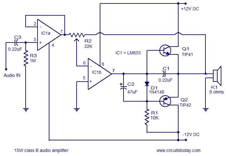
A 15 Watts Class B audio amplifier circuit is designed using a dual op-amp LM833. The schematic diagram is provided, and a potentiometer allows for volume control. The 15 Watts Class B audio amplifier circuit utilizes the LM833 dual operational...