
Audio Tone control in Line amplifier

The circuit described utilizes the LM 1036 integrated circuit (IC) for audio control functions, specifically for volume, balance, and tone adjustments in audio amplification systems. The design emphasizes the integration of minimal external components, which not only simplifies the assembly but also reduces costs by allowing the use of inexpensive monopotentiometers for user adjustments.
The operational functionality of the circuit is enhanced by the inclusion of a loudness control feature, which is activated through switch S1. This switch allows the user to adjust the loudness level according to personal preference or listening conditions, providing flexibility in audio output. The schematic indicates that the loudness control is effectively positioned within the circuit for optimal performance.
In terms of component specifications, the circuit employs resistors R1 to R4, each rated at 47 kOhm, which are crucial for setting the gain levels and ensuring stability within the circuit. Potentiometers P1 to P4, also rated at 47 kOhm, serve as adjustable controls for volume, balance, and tone, allowing for fine-tuning of the audio output.
Capacitors are strategically placed throughout the circuit to filter and stabilize the audio signal. Capacitor C1 has a value of 47 µF, which is likely used for power supply decoupling. Capacitors C2 and C3, each rated at 470 nF, and C4, C5, and C16, rated at 10 nF, are utilized for frequency response shaping and signal coupling. Capacitors C6 and C7, at 10 µF, may serve similar purposes in different sections of the circuit. C8 and C9, rated at 390 nF, along with C10 to C13, rated at 220 nF, further contribute to the signal conditioning necessary for high-fidelity audio reproduction. Finally, capacitors C14 and C15, rated at 4.7 µF, complete the filtering and coupling tasks within the circuit.
The alternative IC option mentioned, the TDA 1524A from Philips, suggests that the design could be adapted or modified based on availability or specific application requirements, providing versatility in audio control system implementations. This design framework ensures that high-quality audio performance can be achieved with a cost-effective and straightforward circuit design.This rule allows the amp volume, balance and tone controls to take. The circuit operates a specially designed IC, LM 1036. The advantage is that few external components and to control monopotmeters can be used, which are cheaper. The schedule speaks for itself. With S1, the loudness can be set. In the drawn position of the loudness. Furthermore, the IC TDA 1524A from Philips same options. Parts List R1-R4 = 47 kOhm P1-P4 = 47 kOhm C1 = 47 uF C2, C3 = 470 nF C4, C5, C16 = 10 nF C6, C7 = 10 uF C8, C9 = 390 nF C10-C13 = 220 nF C14, C15 = 4.7 uF IC1 = LM 1036 🔗 External reference
Related Circuits
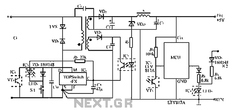
The circuit diagram of the TOPSwitch FZ chip switching power supply is controlled by microcontrollers (MCUs). The microcontroller can be utilized with inkjet printers, laser printers, and other computer peripherals. The TOPSwitch FX, which constitutes the switching power supply...
This project has been on the agenda for some time. The primary concern is that the winch on the Jeep is permanently connected to the battery, allowing unauthorized individuals in parking lots to potentially misuse the winch remote. To...
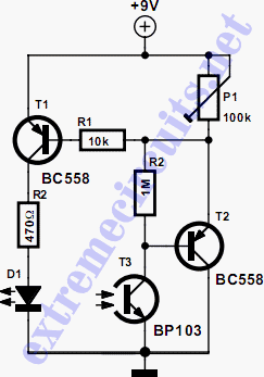
The circuit biases the BC558 transistor, causing LED D1 to flash in response to signals from the remote control. The preset resistor in the circuit sets the sensitivity level. The circuit utilizes a BC558 PNP transistor, which plays a crucial...
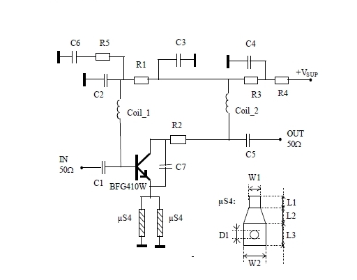
This 900 MHz amplifier circuit is constructed using the BFG480W transistor, which exhibits excellent linearity performance. As a result, the BFG480W is highly suitable for low-noise amplifiers (LNAs) that require high linearity. The 900 MHz amplifier circuit utilizing the BFG480W...
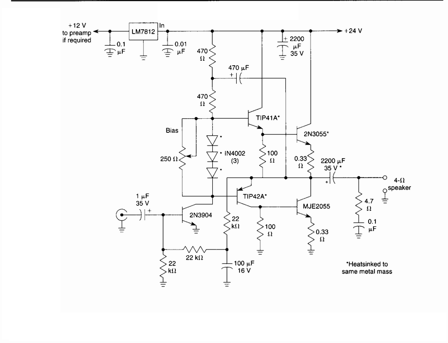
This circuit is a general-purpose 10-W audio amplifier for moderate-power PA or modulator use in an AM transmitter. With higher voltages and a change in bias resistors, up to 30 W can be obtained. The described audio amplifier circuit is...
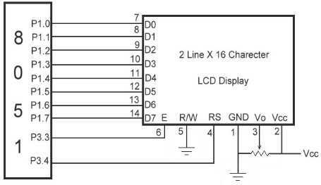
The link shows how to interface Alphanumeric LCD to 8051 Microcontroller. Liquid Crystal Display also called as LCD is very helpful in providing user interface as well as for debugging purpose. The most common type of LCD controller is...