
Graphic Equalizer circuit
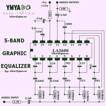
The circuit described is a 5-band graphic equalizer utilizing the LA3600 monolithic linear integrated circuit, which is designed for audio applications requiring frequency response adjustment. The LA3600 features an on-chip operational amplifier that facilitates the formation of a single-channel equalizer by connecting external capacitors and variable resistors. These components are critical for setting the resonance frequency (fo) of each band, allowing for precise audio tuning across the selected frequency ranges.
For enhanced functionality, the circuit can be expanded by connecting two LA3600 ICs in series, enabling the creation of a multiband equalizer with 6 to 10 adjustable frequency bands. This flexibility makes the circuit suitable for various audio devices, including portable component stereos, tape recorders, radio-cassette recorders, and car stereos.
The design ensures high stability when interfaced with capacitive loads, which is essential for maintaining audio fidelity in diverse applications. It is crucial to adhere to the specified voltage limits, with a maximum supply voltage (VCC) of 20V, while the operating voltage should remain within the range of 5 to 15V. Exceeding these voltage parameters may lead to irreversible damage or degradation of the IC.
Care must be taken during the assembly process to avoid unintended short circuits between the pins of the IC. Such shorts can occur due to solder bridges or other conductive materials and can result in failure of the device. Therefore, it is advised to inspect the circuit thoroughly before applying power to ensure that all pin-to-pin spaces are clear of any conductive connections. This attention to detail is vital for the successful operation of the graphic equalizer circuit.This complete high quality, low noise 5-BAND GRAPHIC EQUALIZER circuit is based around Monolithic Linear integrated circuit LA3600 manufactured by SANYO. This circuit is very easy to build and has good Quality. You can use it with Portable component stereos, tape-recorders, radio-cassette recorders, car stereos etc...
It is On-chip one operational amplifier. 5-band graphic equalizer for one channel can be formed easily by externally connecting capacitors and variable resistors which fix fo (resonance frequency). Series connection of two LA3600’s makes multiband (6 to 10 bands) available. It is Highly stable to capacitive load. Maximum supply voltage VCC max 20V must not be exceeded. The operating voltage is in the range of 5 to 15V. Application of power with the pin-to-pin spaces shorted causes breakdown or deterioration of the IC to occur. When mounting the IC on the board or applying power, make sure that the pin-to-pin spaces are not shorted with solder, etc.
🔗 External reference
Related Circuits
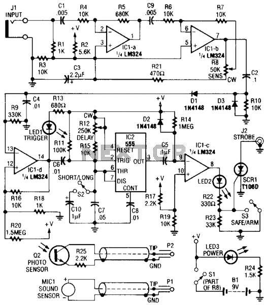
Sound or light sensors connected to J2 produce a voltage that is amplified by IC1-a and IC1-b. A positive trigger voltage developed by D1 and R3, and amplified by IC1-d, drives IC2 and IC1 to trigger SCR1. SCR1 is...
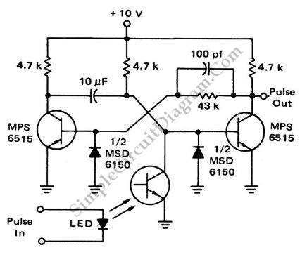
This is a flash-triggered (photo-driven) circuit that produces a pulse with a constant predetermined width. This circuit can be used to control any device. The flash-triggered circuit operates by utilizing a photodetector, which is typically a photodiode or phototransistor, to...
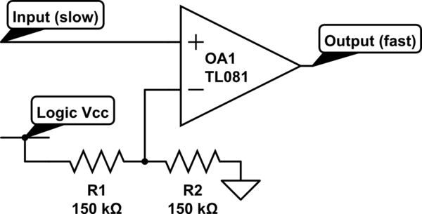
Invert a signal to drive FETs with rapid rise and fall times. It was suggested to use an inverter (not a chip) instead of logic chips, which are designed to be either fully ON or OFF. The individual has...
The circuit described is a simple sound level meter, also known as a VU meter, which helps monitor sound levels to prevent hearing loss caused by loud music. It is a passive type of meter, requiring no separate power...
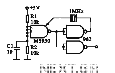
A crystal oscillator is implemented using a DTL (Diode-Transistor Logic) integrated circuit. The oscillation frequencies are 100 kHz and 1 MHz. The circuit consists of a gate circuit that generates a signal for the oscillator circuitry in DTL. The crystal...

This circuit generates a wide variety of noise types, including white noise, pink noise, high pass noise, grainy noise (with adjustable graininess), and adjustable random gates. It is designed for enthusiasts of noise generation. The noise source is derived...