
audio white noise generator

A1 is a voltage follower that buffers the 50% of the battery voltage derived by the two 470k resistors connected to its non-inverting input. The 50% voltage is used as a DC bias supply for the other three amplifiers on the chip.
A2 and A3 provide a gain of 50X each, for a total gain of 2500X. The plot of open loop gain vs frequency for the LM324 shows the bandwidth intercepting the 50X gain point at about 5 kHz, so this filtering provides some "coloration" of the noise. Your choice of headphones or speakers will also color the signal. You can get back some of the bandwidth by putting a small capacitor across one or both of the 20k resistors. Putting a .001 uF capacitor across one of the 20k resistors was about right for the earphones I am using. You can roll the noise off more by putting small (like 5 to 100 pF) across the 1 meg ohm feedback resistors. Don't be afraid to experiment -that's the fun part anyway.
A3 and A4 combine to make a full bridge output. To wit: A4 is a unity gain inverting amplifier that is driven from the output of A3. Since the signal out of A4 is the same as the signal from A3, but inverted, headphones connected across the two outputs will have twice the voltage across them -a handy way to get another 6 dB of gain, but more importantly, a way to avoid using a large coupling capacitor to drive earphones through.
In my setup, I am driving a pair of "ear buds" and I have them connected in series to provide the highest impedance I can get -the LM324s cannot drive much current, but in this full bridge configuration, they can deliver nearly 14 volts peak-to-peak to the load. You can use the circuit to drive an audio amplifier by taking a single-ended output from either A3 or A4. If you decided to drive high impedance speakers directly from the LM342, take a look at the datasheet for the LM324 you plan to use and make sure you don't exceed the maximum rated current, or you might find your rolled-off noise generator to be short lived.
Building it
As with most of my projects, it doesn't need a PC board. I built mine on a piece of perforated PC board and it works fine. Keep it small and tight. In particular, keep the two transistors close to one-another and keep their lead short. The base of the grounded-emitter transistor is a particularly sensitive part of the circuit. The volume control doesn't really need to be on the board (it isn't on mine) since its driven by a low impedance.
The transistors don't have to be 2N4401's. They can be any of a number of small signal NPN transistors. The 2N2222 should work well, for example. The value of the 1 uF capacitors isn't all that important. I chose them for a fast settling time, and the ones in the gain stages (A2 and A3) were chosen for a 10 Hz low frequency rolloff, well below the response of most speakers and headphones. You can use larger values but large capacitors will increase the settling time after the power is switched on. Similarly the resistor values aren't magic - but try to keep in the ballpark and it should work well.
The circuit described is a white noise generator designed to provide a rolled-off noise signal suitable for driving earphones or small speakers. The core of the circuit consists of two transistors (Q1 and Q2) configured to produce broadband noise. Q2 operates as a grounded emitter amplifier, with Q1 configured to avalanche breakdown, generating noise voltage across its junction. The output from Q2 provides the necessary bias current to maintain Q1 in breakdown.
The operational amplifiers (A1, A2, A3, A4) serve to amplify and buffer the generated noise. A1 acts as a voltage follower, providing a stable DC bias derived from a voltage divider, while A2 and A3 amplify the signal by a factor of 50 each, resulting in an overall gain of 2500X. This gain is critical for achieving sufficient output levels for earphones or speakers. The circuit allows for frequency response shaping through the use of capacitors across feedback resistors, enabling customization of the noise character.
The combination of A3 and A4 forms a full bridge amplifier configuration, which enhances the output voltage available to the load while avoiding the need for large coupling capacitors. The design emphasizes compactness, with a recommendation to keep components close to reduce lead inductance and noise susceptibility. The circuit is adaptable, allowing for alternative transistor types and capacitor values, thereby providing flexibility in implementation while ensuring the fundamental operation remains intact. Proper attention to component specifications is necessary to prevent exceeding current ratings, ensuring longevity and reliability of the noise generator.This is a circuit that generates white noise, rolled-off to drive earphones or a small speaker. White noise creates is a "rushing" sound, which sounds something like air rushing by your ear(s). White noise would be flat with frequency, and since this circuit rolls off within the audio range, I refer to it as "rolled-off" noise. White (or rolled-off) noise is said to be useful in helping people improve concentration, to make a "noise wall" to improve privacy, to fill empty spaces with sound so they don't feel so empty (done a lot in larger office buildings) and has been touted as a therapy for Tinnitus (ringing in the ears).
Q2 is a grounded emitter (inverting) amplifier with Q1 in its feedback path. Notice that Q1 is connected kind of "upside down" in that the emitter is positive with respect to its base, so that the junction avalanches, dropping about 5 to 6 volts across the junction. The purpose of Q2 is to provide just enough bias current to make the emitter-base junction of Q1 break down, and under this condition, there is a millivolt or two of broadband noise across the Q2 junction as well.
Note that the collector of Q1 is not connected to anything. In the July 2003 version, the collector of Q1 was connected to the base of Q2, but I have since learned that some transistors exhibit negative impedance characteristics when connected in this manner, so the circuit has been revised to take the current signal from the base instead of the collector. A1 is a voltage follower that buffers the 50% of the battery voltage derived by the two 470k resistors connected to its non inverting input.
The 50% voltage is used as a DC bias supply for the other three amplifiers on the chip. A2 and A3 provide a gain of 50X each, for a total gain of 2500X. The plot of open loop gain vs frequency for the LM324 shows the bandwidth intercepting the 50X gain point at about 5 kHz, so this filtering provides some "coloration" of the noise. Your choice of headphones or speakers will also color the signal. You can get back some of the bandwidth by putting a small capacitor across one or both of the 20k resistors.
Putting a .001 uF capacitor across one of the 20k resistors was about right for the earphones I am using. You can roll the noise off more by putting small (like 5 to 100 pF) across the 1 meg ohm feedback resistors.
Don't be afraid to experiment -that's the fun part anyway. A3 and A4 combine to make a full bridge output. To wit: A4 is a unity gain inverting amplifier that is driven from the output of A3. Since the signal out of A4 is the same as the signal from A3, but inverted, headphones connected across the two outputs will have twice the voltage across them -a handy way to get another 6 db of gain, but more importantly, a way to avoid using a large coupling capacitor to drive earphones through. In my setup, I am driving a pair of "ear buds" and I have them connected in series to provide the highest impedance I can get -the LM324s cannot drive much current, but in this full bridge configuration, they can deliver nearly 14 volts peak-to-peak to the load.
You can use the circuit to drive an audio amplifier by taking a single-ended output from either A3 or A4. If you decided to drive high impedance speakers directly from the LM342, take a look at the datasheet for the LM324 you plan to use and make sure you don't exceed the maximum rated current, or you might find your rolled-off noise generator to be short lived.
Building it As with most of my projects, it doesn't need a PC board. I built mine on a piece of perforated PC board and it works fine. Keep it small and tight. In particular, keep the two transistors close to one-another and keep their lead short. The base of the grounded-emitter transistor is a particularly sensitive part of the circuit. The volume control doesn't really need to be on the board (it isn't on mine) since its driven by a low impedance. The transistors don't have to be 2N4401's. They can be any of a number of small signal NPN transistors. The 2N2222 should work well, for example. The value of the 1 uF capacitors isn't all that important. I chose them for a fast settling time, and the ones in the gain stages (A2 and A3) were chosen for a 10 Hz low frequency rolloff, well below the response of most speakers and headphones.
You can use larger values but large capacitors will increase the settling time after the power is switched on. Similarly the resistor values aren't magic - but try to keep in the ballpark and it should work well.
🔗 External reference
Related Circuits
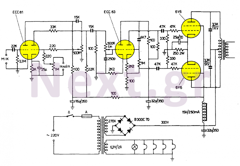
These two amplifiers are of high quality, simple, and economical to manufacture. They feature two inputs: one for a 4mV (500KΩ) sensitivity microphone and another for any 200mV (1MΩ) sound source, with the first input designated for speech and...
The original scale on the voltmeter ranged from 0 to 30 volts. A new scale was created by removing the old scale from the meter and scanning it into a graphics editing software on a computer. The old numbers...
This works with a small geleidingstestertje LM 3909. It allows a tester beeps when the resistance between the probes between 0 and 100 ? lies. Due to the volume of the beep, the resistance between the probes can be...
The 60 Hz frequency generator circuit is essential for creating inverters or hardware related to AC current voltage. This 60 Hz frequency generator is straightforward and highly accurate, producing a precision square wave output. The core of this generator...
Given the variety of equipment in modern home entertainment systems, the ability to adjust the gain of both audio and video signals has become essential. This particular circuit has proven to be very useful when used alongside the General...
Building your own Zapper. It requires one capacitor of 1 microfarad (C2), preferably unpolarized to eliminate concerns regarding positive and negative terminals. If a polarized capacitor is used, the longer leg indicates the positive side; refer to the schematic...