
Frequency Generator:
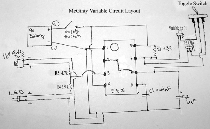
To connect R1, a 3.3k resistor, one end is attached to pin 8 and the other to pin 7. The resistor legs are bent over the pins, cut to 1/4 inch longer than the distance to the pin, then inserted into the pin holes as shown in the schematic. Proper soldering is crucial; ensure clean and accurate connections to prevent circuit failure. Overlapping solder can be corrected by heating the connection and using another wire to absorb excess solder. It is advisable to heat the wires before applying solder for cleaner results, which improves with practice.
The final circuit is prepared for enclosure, with LED wires routed to the outside for connection. Shrink tubing is used to insulate connections and prevent contact with other wires. Holes are drilled for switches, LEDs, and output jacks, with space reserved for two 9-volt batteries to extend operational time, approximately 14 days at 15 Hz. The frequency box is designed for powering devices rather than for use with electrodes for body parasite elimination. A digital voltage meter from Radioshack, priced around $50, is recommended for measuring frequencies by connecting the generator output to the meter’s input. For frequency setting, a computer is used with a 1/8" stereo jack connected to the sound card, ensuring low input volume. A sound generator program is employed to match tones, with the sound wave configured to square.
The schematic for the Zapper circuit includes all necessary components and connections, ensuring accurate assembly and functionality. The use of variable potentiometers allows for customizable frequency settings, enhancing the device’s versatility. Proper soldering techniques and careful component placement are essential for reliable operation, while the enclosure design facilitates easy access to controls and power sources. The inclusion of a voltage meter aids in frequency verification, ensuring precise operation of the Zapper.Building your own Zapper. 1 Compositor 1 micro farad, C2, I like the un-polarized because it allows you not to worry about positive an negative sides. If you do get one with a longer leg that`s the positive, see schematic for proper placement. 1 resistor for R2 see Fredbuster`s PDF file for specific resistor for frequency. I use variable potentiometers because I like to set exact frequencies myself. I use 100k potentiometers, they give me a range from 6hz to 460hz when adjusting. You can see in the below photo I have both the large audio and micro potentiometers. The micro is used to be set at 15hz and the Audio is for creating variable. Black and Red 22 gauge connecting wire, Make sure its the one with multiple threads of copper and not a solid one. Its easier to bend and move. The solid copper connecting wire is to kinky and breaks to easily, for my taste. Next we attach R1 3. 3k resistor. One end goes to pin 8 and the other to pin 7, I bend the legs over the pin then cut off 1/4" longer than the distance to the pin.
the remaining 1/4" I bent over and stick in the pin hole. see schematic. You can see how I soldered the connections together. Make sure you are clean and accurate. Other wise a lose connection or overlapping solder will cause the circuit not to work. This takes patients and time, don`t rush it. If you do overlap a connection with solder, heat it up, use another wire to suck up the excess and then use a knife to remove the last bits. I heat the wires first then add the solder. It`s cleaner once you get used to soldering. Takes practice. Here is what the final circuit looks like before it`s place in a box. You can see the R2 I added here. I use a toggle switch to go back and forth between the set resistor and variable resistor. One end of the resistor is connected to R1 where it attaches to pin 7. The middle Pin on the Potentiometer is then connected to a toggle switch. The Middle switch pin is then connected to C2 where it attaches to pin 6. Using potentiometers allows you to set a frequency you want. In Fredbusters tutorial he gives you the specific resistor for specific frequency. Here are links to four photos showing detailed enlargement of the circuit with the variable potentiometers added and how they are connected.
This should explain how I connected the potentiometers. Next I begin placing the circuit into the box. I slip the LED wires thru to the outside because that`s how you hook up this specific light. I used shrink tubing to seal the connection keeping them not from touching other wires. You can see how I drilled the holes to fit each switch, LED and output jack. This is how I have the circuit placed inside the box. Notice the blank area to hold the two 9 volt batteries. I prefer two 9v because it allow the Freq Gen to run longer. About 14 days nonstop at 15hz. And finally how the frequency box looks when finished. Notice I don`t have penny electrodes because this box is only to power OR devices and not kill body parasites. Copy the circuit drawing above and you can have both. Radioshack sells a digital voltage meter which has a setting for frequencies. It cost me about $50. It works great. All I do is connect the output from the generator to the meterG•s input wires. Instantly it says the exact frequency the dial is tuned too. If you donG•t have voltage meter and work around the house repairing things yourself this is a must have.
To put the set the frequencies I use my computer. I use the 1/8" stereo jack into my sound card, making sure the input volume is on low. Use a Sound generator program and match the tones. Make sure the sound wave is set to square. It takes time to get it right but it works. With help from CBSWORK I have been testing music notes to chakras and 🔗 External reference
Related Circuits
Built around an Intersil 7216 frequency counter IC, this counter has a basic range of 10 MHz, a 100-MHz prescaler, and an extra frequency divider (IC3). This divider reduces the frequency by an additional factor, as indicated on S7...
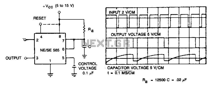
If the input frequency is known, the timer can be utilized as a frequency divider by adjusting the duration of the timing cycle. The figure illustrates the waveforms of the timer when employed as a divide-by-three circuit. This application...
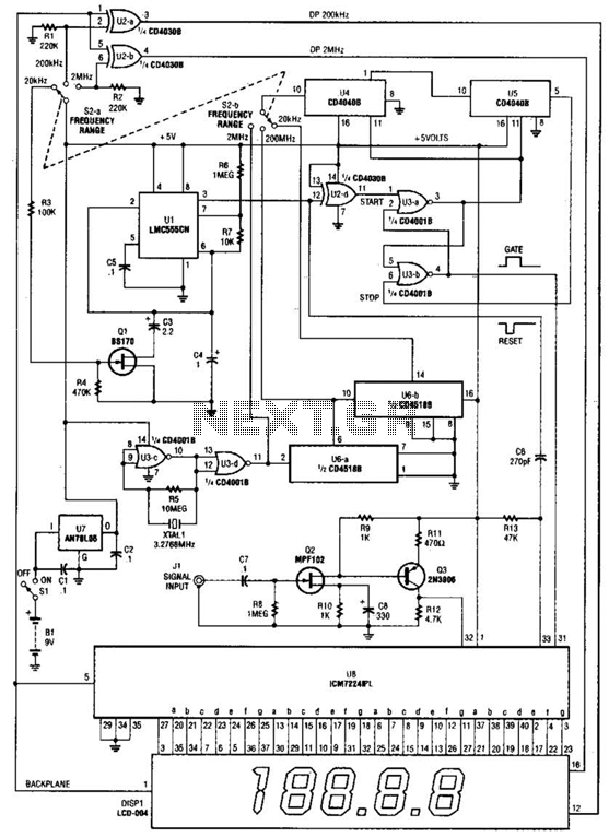
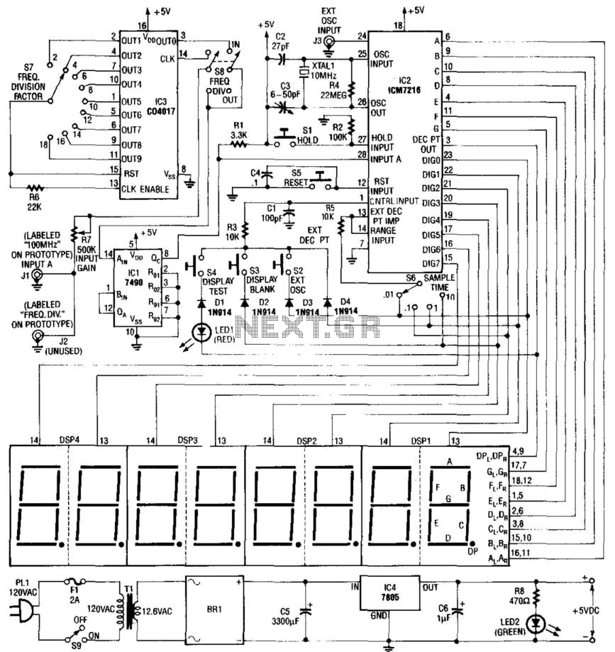
This is a schematic and block diagram of a 2-MHz frequency counter. It utilizes an LSI counter/display driver, an LCD readout, and several logic chips for timebase and timing pulse circuitry. Q2 and Q3 serve as a signal (input)...
The simple circuit does not provide isolation; however, its simplicity, combined with the affordability of sound cards and the protective features added by diodes 1 and 2, makes it suitable for the average user. The physical hardware includes a...
This sound frequency meter circuit is simple to build and can be constructed in a portable format. It can measure frequencies with a minimum level of 10 mV. The sound frequency meter circuit is designed to provide an effective and...
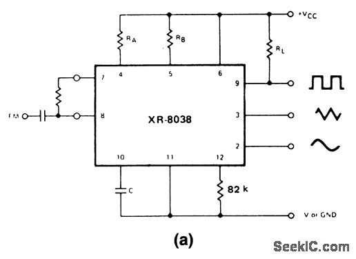
These circuits are similar to that of Fig. 5-47, except that they provide for FM or sweep modulation. Circuit 5-50A is used for FM with small deviations, approximately ±10%. Circuit 5-50B is designed for a sweep range of 1000:1....