
Digital Volume Control
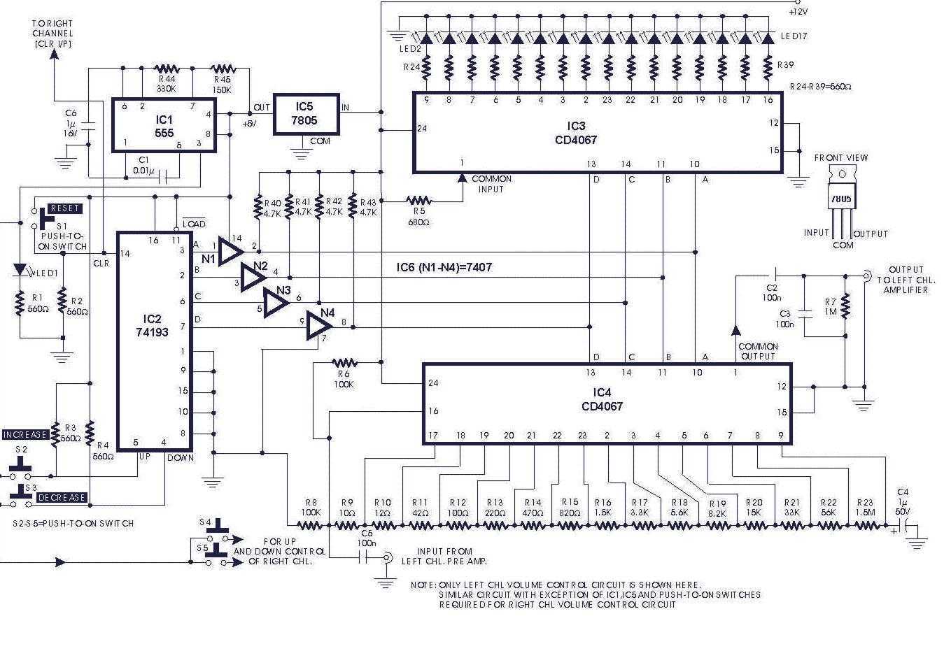
The circuit described is a digital volume control system that utilizes six integrated circuits (ICs) to manage audio levels electronically. The main components include a 555 timer configured as an astable multivibrator (IC1), which generates a square wave signal. The frequency of this signal can be modified by selecting appropriate resistor values (R44, R45) and a capacitor (C6), allowing for a period of 0.3 seconds as specified.
IC2 serves as a presetable up/down counter, which is essential for tracking the volume changes. In this configuration, the up mode increments the volume while the down mode decrements it, providing a straightforward user interface for volume adjustments. The counter's output is in Binary-Coded Decimal (BCD) format, making it suitable for digital applications.
Analogue multiplexers IC3 and IC4 play critical roles in the circuit. IC3 is utilized as a level indicator, likely providing visual feedback on the current volume level, while IC4 acts as a digital potentiometer, facilitating smooth transitions in volume levels without the mechanical wear associated with traditional potentiometers.
The system initialization requires the pressing of switch S1, which resets the entire circuit to a known state. Subsequently, switch S2 can be activated to enable the counting process, allowing the user to adjust the volume by counting the pulses generated by the 555 timer.
Finally, IC6 functions as an interface between TTL (Transistor-Transistor Logic) and CMOS (Complementary Metal-Oxide-Semiconductor) technologies, ensuring compatibility between different logic levels in the circuit. This integration of components results in an efficient and reliable digital volume control system suitable for various audio applications.Circuit of a digital volume control using six discrete ICs, including a 5V regulator, is presented. IC1 (555) is configured to function as astable flip-flop. Its frequency or period may be adjusted by proper choice of resistors R44, R45 and capacitor C6 combination. Here it is for 0.3 second period. IC2 is a presetable up/down counter. In this circuit up-mode is used for increasing and down-mode is used for decreasing the volume. IC3 and IC4 are 16-channel analogue multiplexers which function as analogue switches. Here IC3 is used as level indicator while IC4 is used as a potentiometer. Soon after the power is switched on, switch S1 is to be pressed to reset the whole system. When switch S2 is pressed, IC2 counts up the number of pulses and the result is available in the form of BCD output. IC6 is used as an interface between TTL and CMO 🔗 External reference
Related Circuits
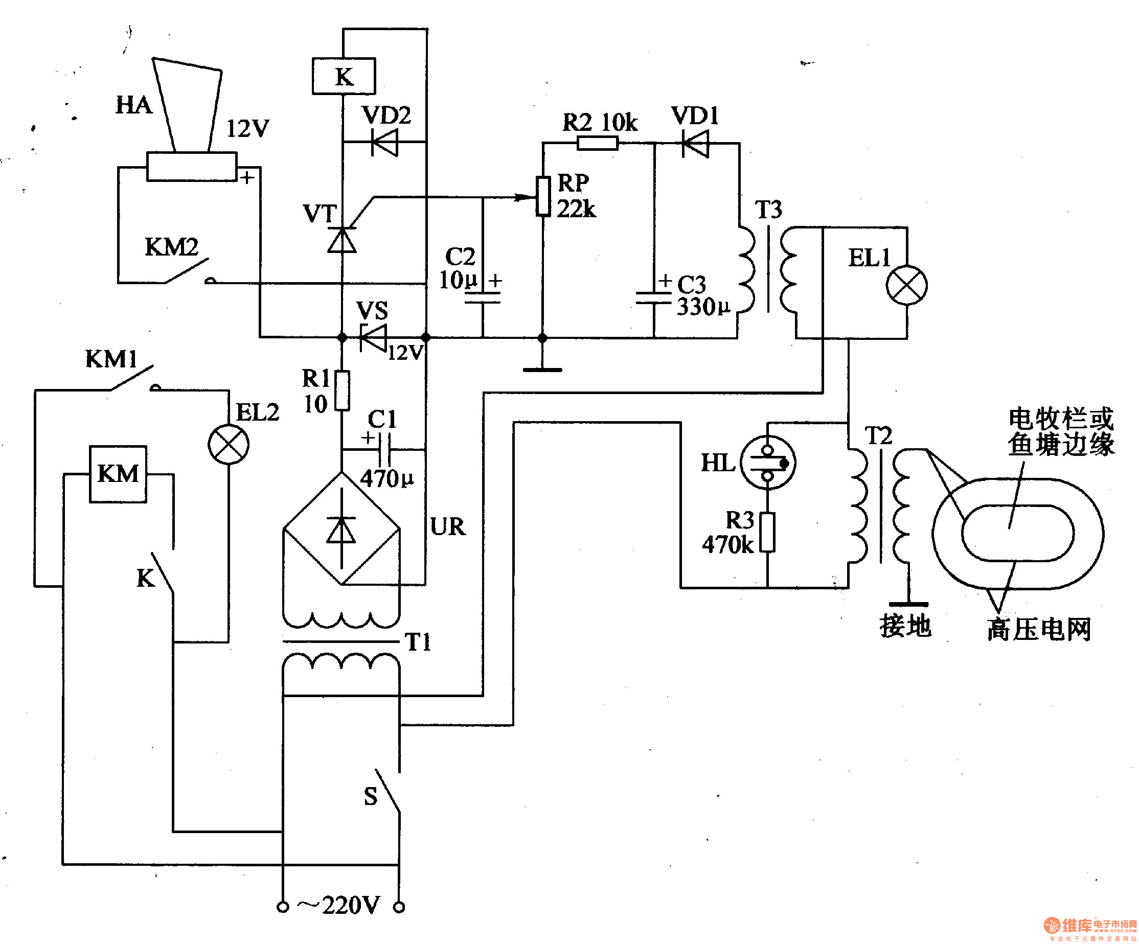
The electric fence control circuit consists of three main components: the power supply circuit, the high voltage circuit, and the sound and light alarm circuit, as illustrated in Figure 4-26. The power supply circuit includes a power switch (S),...
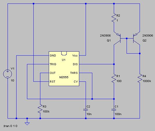
The typical BPM range for music is between 40 and 240 BPM, corresponding to periods of 1500 ms and 200 ms, respectively. A BPM of 120 equates to a period of 500 ms. The circuit requires a resistor R4...
This circuit is designed for precise centigrade temperature measurement. It features a transmitter section that converts the sensor's output voltage, which is proportional to the measured temperature, into frequency. The output frequency bursts are transmitted through the mains supply...
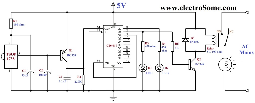
An infrared (IR) remote control circuit for managing home appliances can be constructed using a Decade Counter CD4017, a 555 Timer, and a TSOP1738 infrared receiver. This circuit allows users to control home devices with a standard remote control,...
To explain in a little more detail, using the ATMEGA8's internal 2.5 volt band gap reference means that by using a resistive divider ahead of the A-to-D converter, the input could be scaled such that any voltage range from...
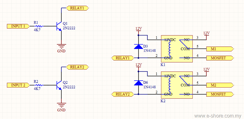
The circuit utilizes two sets of relays for each motor to switch the motor's direction, and one set of MOSFETs for each motor to control the motor's speed. The MOSFET and relay circuit will be divided into three parts...