
Auto Generator Regulator Circuit
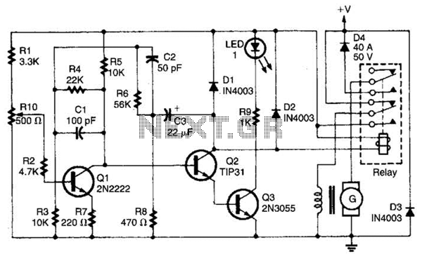
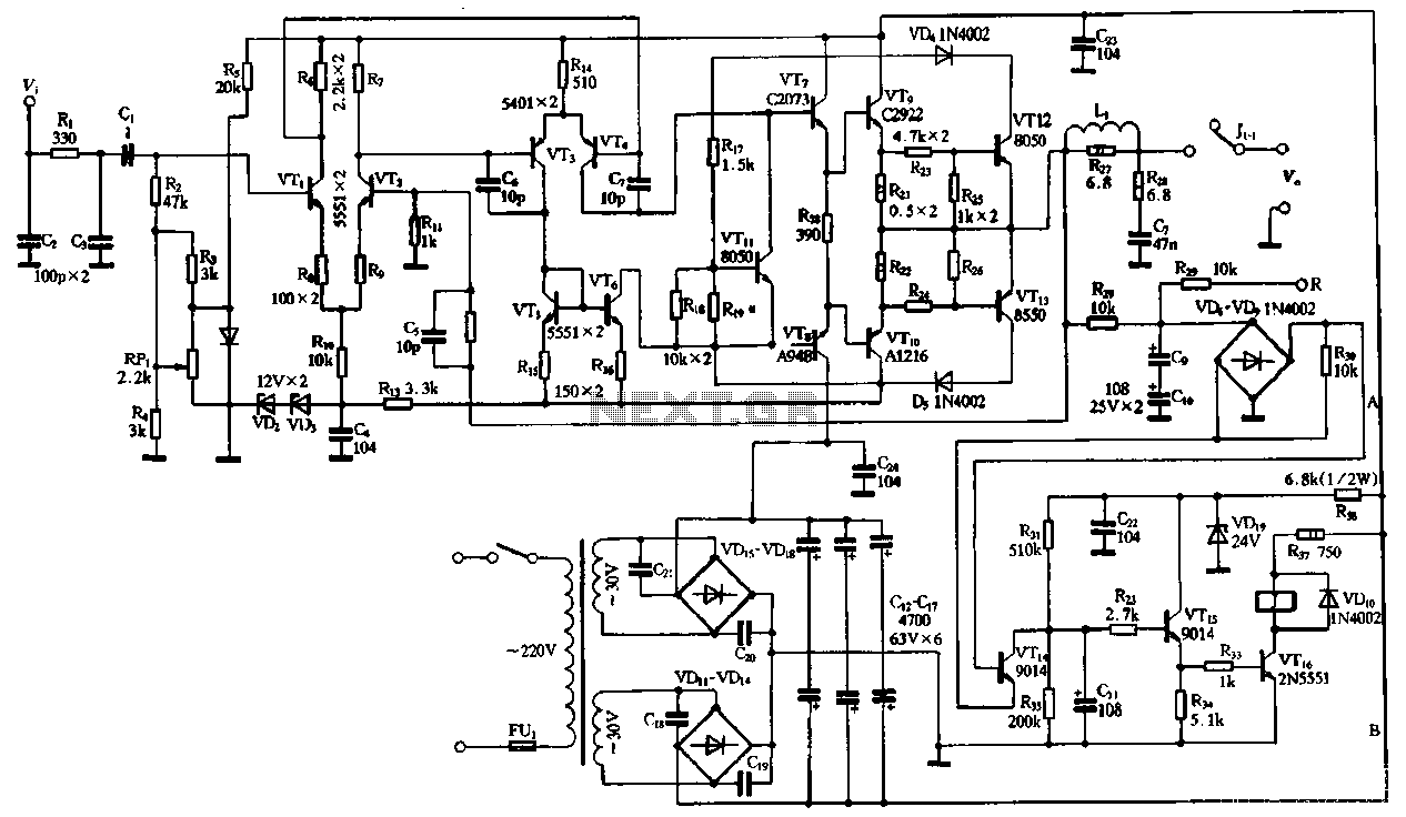
The described DC generator regulator circuit plays a crucial role in maintaining the efficiency and reliability of a DC power generation system. The grounding of one side of the field winding is a common practice that helps stabilize the magnetic field and enhances the overall performance of the generator.
Diode D4 is strategically placed in the circuit to ensure that the battery does not discharge back through the generator, which could lead to battery depletion and inefficient operation. By replacing the mechanical cut-out relay, D4 provides a more reliable and faster response to changes in voltage and current, thus improving the overall safety and functionality of the system.
The RIO, or Regulator Input Output, is an adjustable component that allows for fine-tuning of the system voltage. This feature is essential for adapting the output voltage to meet varying load requirements and ensuring that the connected devices receive the appropriate voltage for optimal performance. The ability to adjust the voltage setting can also help in protecting sensitive electronic components from overvoltage conditions.
In summary, the combination of the grounded field configuration, the protective function of diode D4, and the adjustable RIO setting creates a robust and efficient DC generator regulation system that enhances the performance and longevity of the power generation setup. This regulator is for the purpose of controlling a dc generator. The field configuration is that one side of the field is grounded. D4 prevents the battery from discharging through the generator and takes the place of the mechanical cut-out relay. RIO adjusts the system voltage setting. 🔗 External reference
Related Circuits
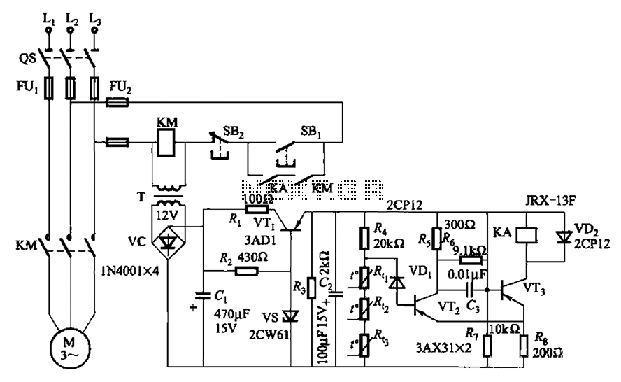
A P-type transistor (VT2, VT3) and other components form a common emitter-coupled trigger, functioning as a Schmitt trigger device. This setup serves as a switching circuit to detect changes in the resistance of a PTC thermistor, thereby controlling the...
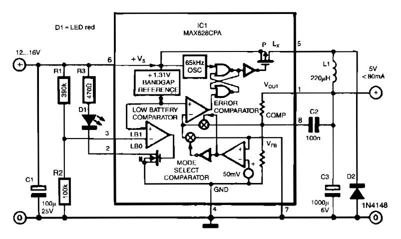
The circuit is straightforward due to the use of the MAX638CPA 5V CMOS Step Down Adjustable Switching Regulator IC. This IC converts an input voltage of 12 to 16 VDC into a stable 5VDC output. The circuit requires only...
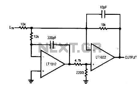
The circuit comprises a low drift LT1012 device and a high-speed amplifier LT1022. It functions as a unity gain inverter, with the summing node located at the junction of three 10k ohm resistors. The circuit monitors the summing node...
The performance of the amplifiers 2SC2922 and 2SA1216 (or 2SC3264 and 2SA1295) is excellent, featuring good linearity and strong overload capabilities. These devices are utilized as high-fidelity power amplifier stages, demonstrating outstanding performance. The circuit, as illustrated in Figure...
The circuit presented is a standard Colpitts oscillator, commonly utilized in many amateur radio homebrew transmitters. This specific circuit is designed to operate effectively within a frequency range of 1500 kHz to 8000 kHz. To accommodate lower frequencies, it...
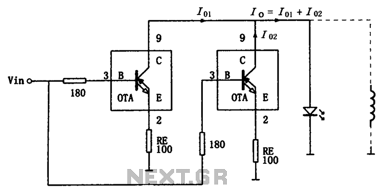
The high-speed parallel current drive circuit utilizes the OPA660 operational transconductance amplifier (OTA). An input signal, Vin, is connected to a 180-ohm resistor equivalent device at the base (pin 3) of the OPA660. The collector (pin 8) is directly...